Dear Mr. Electrician: Where can I find single-phase electric motor diagrams?
Answer: I have compiled a group of single-phase electric motor diagrams and terminal connections below. At the bottom of this post is a video about DC shunt motors.
NOTE: Some text links below go to applicable products sold on Redbubble, Amazon, and eBay. As an Amazon Associate, I earn from qualifying purchases. Using my links helps to keep this website FREE.
Table of Contents:
- TERMINAL CONNECTIONS FOR CAPACITOR START MOTORS
- ELECTRIC MOTOR DIAGRAMS
- SPLIT-PHASE INDUCTION MOTOR
- SPLIT-PHASE PERMANENTLY CONNECTED CAPACITOR MOTOR
- SPLIT-PHASE CAPACITOR START MOTOR
- SPLIT PHASE CAPACITOR-RUN MOTOR
- ANOTHER SPLIT-PHASE CAPACITOR-RUN MOTOR
- SPLIT-PHASE CAPACITOR-RUN REVERSIBLE INDUCTION MOTOR
- REACTOR-START MOTOR
- SPLIT-PHASE SINGLE-VALUE CAPACITOR DUAL VOLTAGE MOTOR
- REPULSION MOTOR
- REPULSION-START MOTOR
- SHADED POLE MOTOR
- SKELETON-TYPE SHADED POLE MOTOR
- UNIVERSAL MOTOR
- MOTOR FRAME SIZES
- DC MOTOR INFORMATION
TERMINAL CONNECTIONS FOR CAPACITOR START SINGLE-PHASE MOTORS
Motor Rotation Terminal Connections - Single Voltage
| ROTATION | L1 | L2 |
|---|---|---|
| Clockwise | 1,5 | 4,8 |
| Counter Clockwise | 1,8 | 4,5 |
Motor Rotation - Dual Voltage, Main Winding Only
| VOLTAGE | ROTATION | L1 | L2 | JOIN |
|---|---|---|---|---|
| High | CCW | 1 | 4, 5 | 2 & 3 & 8 |
| High | CW | 1 | 4, 8 | 2 & 3 & 5 |
| Low | CCW | 1, 3, 8 | 2, 4, 5 | - |
| Low | CW | 1, 3, 5 | 2, 4, 8 | - |
Motor Rotation - Dual Voltage, Main & Auxiliary Windings
| VOLTAGE | ROTATION | L1 | L2 | JOIN |
|---|---|---|---|---|
| High | CCW | 1, 8 | 4, 5 | 2 & 3, 6 & 7 |
| High | CW | 1, 5 | 4, 8 | 2 & 3, 6 & 7 |
| Low | CCW | 1, 3, 6, 8 | 2, 4, 5, 7 | - |
| Low | CW | 1, 3, 5, 7 | 2, 4, 6, 8 | - |
The auxiliary winding switch connections must be made so that both auxiliary windings become de-energized when the switch opens.
ELECTRIC MOTOR DIAGRAMS
Internal Wiring Diagrams of Small and Fractional Horsepower Electric Motors
SPLIT PHASE INDUCTION SINGLE PHASE MOTOR DIAGRAM
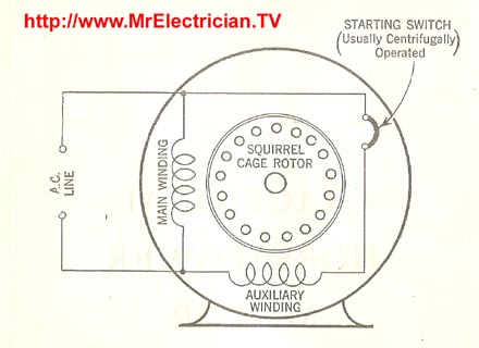
The Split Phase Induction Electric Motor has a squirrel-cage rotor for constant speed operation. It has a starting winding of high resistance, which is physically displaced in the stator from the main winding.
In series with the starting winding is a centrifugal starting switch, which opens the starting circuit when the motor has attained approximately 75 to 80 percent synchronous speed. The function of the starting switch is to prevent the motor from drawing excessive current and protect the starting winding from excessive heat. The motor may be started in either direction by reversing the main or the auxiliary (Starting) winding.
These motors are suitable for oil burners, blowers, business machines, buffing machines, grinders, etc.
SPLIT PHASE PERMANENTLY CONNECTED CAPACITOR MOTOR
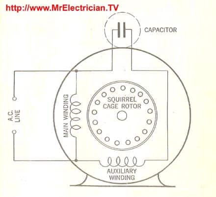
A Split Phase Permanently Connected Capacitor Electric Motor also has a squirrel-cage rotor with a main and starting winding. A capacitor is permanently connected in series with the auxiliary winding. Motors of this type start and run with a fixed capacitance value in series with the starting winding.
The motor obtains its starting torque from a rotating magnetic field produced by the physically displaced two stator windings. The main winding is connected directly across the line, while the auxiliary or starting winding is connected to the line through the capacitor, giving an electrical phase displacement.
This motor is good for directly connected drives requiring low starting torque, such as fans, blowers, and some pumps.
SPLIT PHASE CAPACITOR START MOTOR
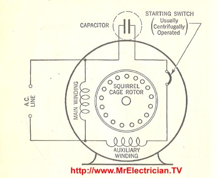
A split-phase capacitor starter electric motor may be defined as a form of a split-phase motor having a capacitor connected in series with the auxiliary winding. The centrifugal switch opens the auxiliary circuit when the motor reaches 70 to 80 percent of synchronous speed.
It is also known as a capacitor-start, induction-run motor. The rotor is a squirrel cage. The main winding is connected directly across the line, while the auxiliary or starting winding is connected through a capacitor, which may be connected to the circuit through a transformer with suitably designed windings and capacitors of such values that the two windings will be approximately 90 degrees apart.
Motors of this type are suited for air conditioning and refrigeration applications, belt-driven fans, etc.
SPLIT PHASE CAPACITOR RUN SINGLE PHASE MOTOR DIAGRAM
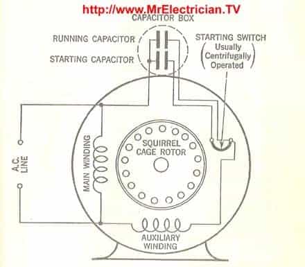
Split Phase Capacitor Run Electric Motor. A split-phase capacitor run electric motor has a running capacitor permanently connected in series with the auxiliary winding. The starting capacitor is in parallel with the running capacitor only during the starting period. The motor starts when the centrifugal switch is closed.
CLICK HERE for Electric Motors and Accessories on Amazon
After the motor reaches 70 to 80 percent of synchronous speed, the starting switch opens and disconnects the starting capacitor. The running capacitor is usually paper-spaced, oil-filled, and typically rated at 330-volt AC for continuous operation. They can range from 3 to 16 micro-farads.
The starting capacitor is generally electrolytic and may range from 80 to 300 micro-farads for 110-volt 60 HZ motors.
These motors are suitable for high-starting torque applications, such as compressors, loaded conveyors, reciprocating pumps, refrigeration compressors, etc.
ANOTHER SPLIT-PHASE CAPACITOR RUN MOTOR
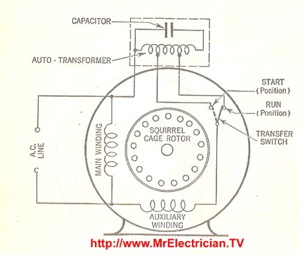
Another split-phase capacitor run type of electric motor utilizes a capacitor transformer unit. It is of the split-phase squirrel cage type, with the main and auxiliary windings physically displaced in the stator. It uses a single pole double throw transfer switch to impress a high voltage across the capacitor during start-up.
After the motor has attained 70 to 80 percent of synchronous speed, the transfer switch operates to change the voltage taps on the transformer. The voltage supplied to the capacitor through the transformer can vary between 600 and 800 volts during start-up. For continuous operation, around 350 volts is furnished.
It is suitable for high-starting-torque applications such as compressors, loaded conveyors, reciprocating pumps, refrigeration compressors, etc.
SPLIT PHASE CAPACITOR RUN REVERSIBLE INDUCTION MOTOR
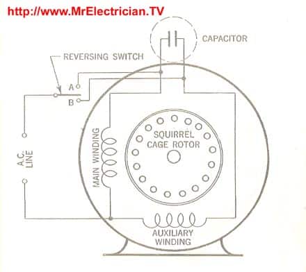
A Split Phase Capacitor-Run Induction Electric Motor (Reversible). When the reversing switch is in the “B” position, the auxiliary winding becomes the main winding, and the main winding becomes the auxiliary. The windings function in the diagram in the “A” position.
In split-phase motors, changing the winding causes the motor to work in reverse. The wire size and number of turns must be identical in both windings.
Use this when you need a reversible high-torque, intermittently rated capacitor-type motor.
This Motor wiring diagram is available on tee shirts, coffee mugs, stickers, hoodies, mini-skirts, magnets, and more.
REACTOR START SPLIT PHASE INDUCTION MOTOR
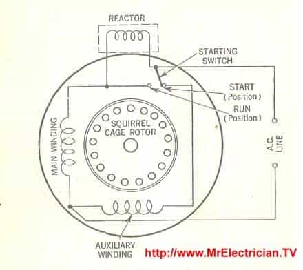
Reactor Start Split Phase Induction Electric Motor. This motor is equipped with an auxiliary winding, displaced in magnetic position from, and connected in parallel with the main winding. The reactor reduces the starting current and increases the current lag in the main winding.
At approximately 75% synchronous speed, the starting switch shunts the reactor, disconnecting the auxiliary winding from the circuit.
This constant-speed motor is best for light-running fans, small blowers, business machines, grinders, etc.
This motor diagram is available on tee shirts, coffee mugs, stickers, mini-skirts, phone cases, tote bags, caps, tool pouches, and more.
SPLIT PHASE SINGLE VALUE CAPACITOR DUAL VOLTAGE MOTOR
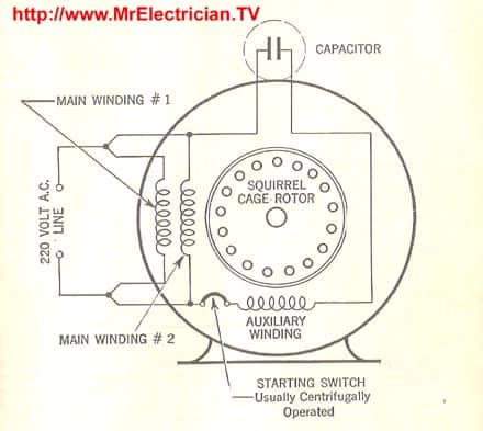
Split Phase Single Value Capacitor Electric Motor (Dual Voltage Type). This motor has two identical main windings arranged for either series or parallel connections. With the main windings connected in parallel, the line voltage is usually 240. When the main windings are connected in series, 120 volts is used.
The auxiliary starting winding is displaced in space from the main winding by 90 degrees. It also has a centrifugal switch and starting capacitor. This winding arrangement gives only half as much starting torque at 120 volts as on a 240-volt connection.
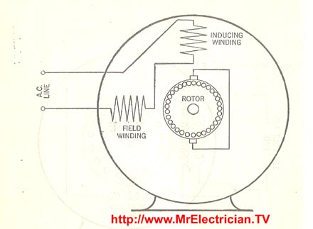
A Repulsion Electric Motor is, by definition, a single-phase motor with a stator winding arranged for connection to the source of power and a rotor winding connected to a commutator. Brushes and commutators are short-circuited and placed so that the magnetic axis of the rotor winding is inclined to the magnetic axis of the stator winding.
It has a varying speed characteristic, a high starting torque, and a moderate starting current. Due to its low power factor except at high speeds, it can be modified into a compensated repulsion motor that has another set of brushes placed midway between the short-circuited set. This added set is connected in series with the stator windings.
REPULSION START REVERSIBLE INDUCTION MOTOR
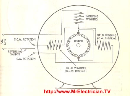
Repulsion Start Induction Electric Motor (Reversible) A repulsion start induction motor is a single-phase motor having the same winding as a repulsion motor. Still, at a predetermined speed, the rotor winding is short-circuited or connected to give the equivalent of a squirrel cage winding.
This motor starts as a repulsion motor but operates as an induction motor with constant speed characteristics. It has a single-phase distributed field winding with the brushes’ axis displaced from the field winding’s axis. The armature has an insulated winding. The current induced in the armature is carried by the brushes and commutator, resulting in high starting torque.
When nearly synchronous speed is reached, the commutator is short-circuited so that the armature is similar in its functions to a squirrel cage armature. The diagram depicts a reversible type with two stator windings displaced as indicated. Reversal of the motor is accomplished by interchanging the field winding connections.
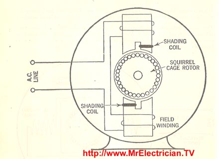
A Shaded Pole Electric Motor is a single-phase induction motor with an auxiliary short-circuited winding or windings displaced in a magnetic position from the primary winding. Some different construction methods are used, but the basic principle is the same.
The shading coil consists of low-resistance copper links embedded in one side of each stator pole and provides the necessary starting torque. When the current increases in the primary coils, a current is induced in the shading coils that oppose the magnetic field, building up in part of the pole pieces they surround.
When the primary coil current decreases, the shading coil decreases until the pole pieces are uniformly magnetized. As the primary coil current and the pole piece magnetic flux continue to decrease, the current in the shading coils reverses and tends to maintain the flux in part of the pole pieces.
When the primary coil current drops to zero, current still flows in the shading coils to give the magnetic effect, which causes the coils to produce a rotating magnetic field, which makes the motor self-starting.
Used where the power requirements are small, such as clocks, instruments, hair dryers, small fans, etc.
SKELETON-TYPE SHADED POLE MOTOR
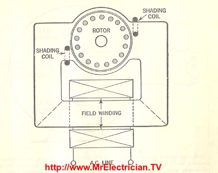
Skeleton Type Shaded Pole Electric Motor. A Skeleton Type Shaded Pole Electric Motor is built for applications where the power requirements are minimal. The field circuit, with its winding, is built around the conventional squirrel cage rotor and consists of punchings stacked alternately to form overlapping joints in the same manner that small transformer cores are assembled.
Motors like this will only operate on alternating current (AC). They are simple in construction, low in cost, and highly rugged and reliable. Their principal limitations are, however, low efficiency and a low starting and running torque.
A shaded pole motor is not reversible unless shading coils are provided on each side of the pole and means for opening one and closing the other coil are provided. The inherently high slip of a shaded pole motor makes it convenient to obtain speed variation on a fan load, for example, by reducing the voltage.
CLICK HERE for Manual Motor Starters on eBay
UNIVERSAL ELECTRIC MOTOR DIAGRAM

A Universal Electric Motor is designed to operate on alternating or direct currents (AC/DC). It is a series wound motor. It is provided with a field winding on the stator, connected in series with a commutating winding on the rotor. Commonly manufactured in fractional horse-power sizes.
Full load speeds generally range from 5000 to 10,000 RPMs, with no-load speeds from 12,000 to 18,000 RPMs. Typical uses include portable tools, office appliances, electric cleaners, kitchen appliances, sewing machines, etc.
The speed of universal motors can be adjusted by connecting a resistance of proper value in series with the motor. This makes it suitable for such applications as sewing machines that operate over various speeds. Universal motors may be compensated or uncompensated for higher speeds and lower ratings only.
An interchange of the brush holder accomplishes reversal of this motor leads with the armature connected to the neutral wire. In the split-series, three-wire reversible type universal motor, one stator coil is used to obtain one direction and the other stator coil to obtain the other direction, with only one stator coil being in the circuit at a time. The armature connections must be connected to the neutral wire to obtain satisfactory operation in both rotation directions.
Get the Universal Motor Diagram on mugs, tee shirts, stickers, magnets, hoodies, and more.
FRAME SIZES
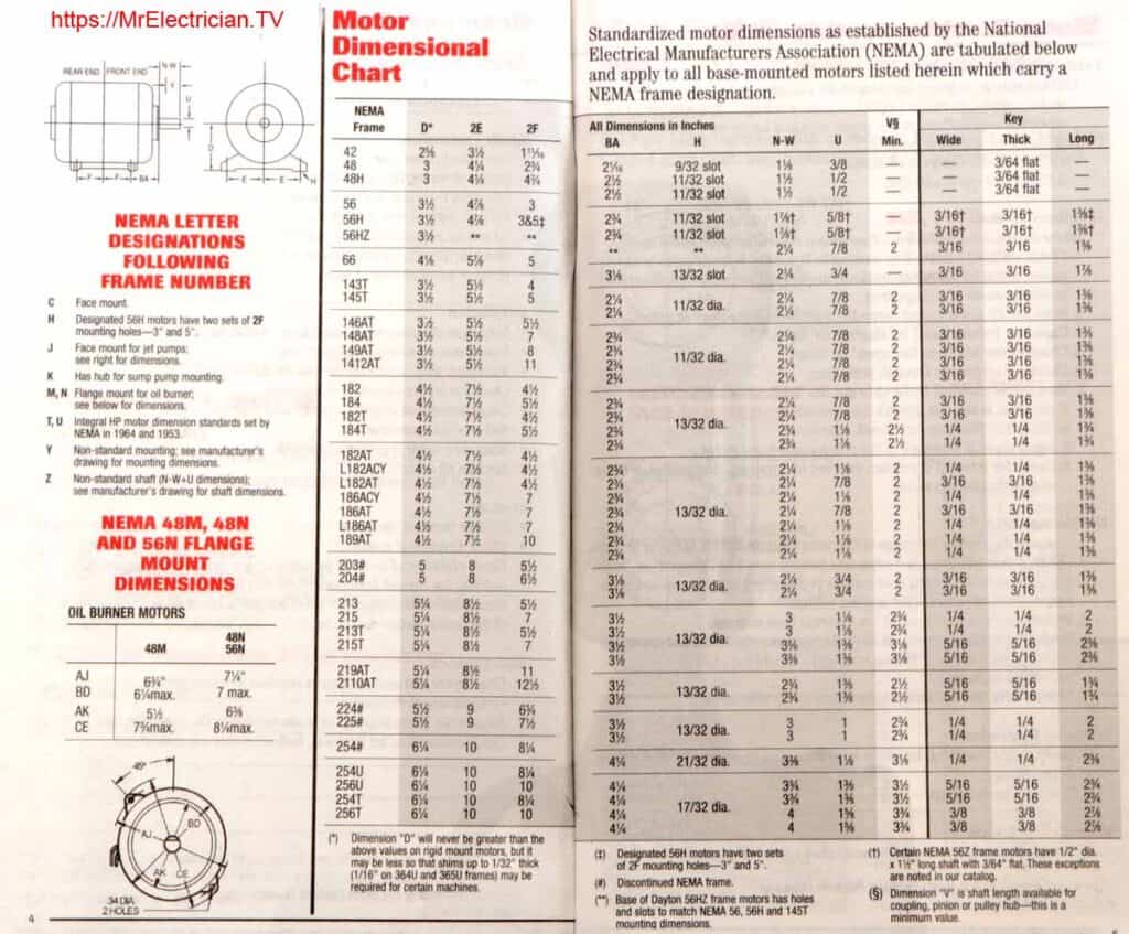
Below is a motor frame size dimensional chart I found in an old book.
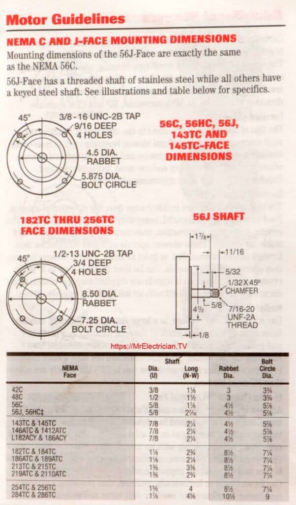
I found this information about motor mounting dimensions in the same book.
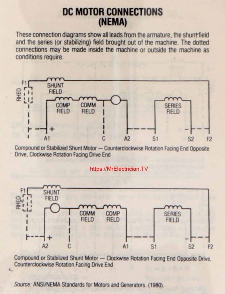
SOME DC MOTOR INFORMATION

Comprehensive information on the operation, repair, and history of electric motors can be found on this industry website post. Click on “Articles” when you get there or scroll down for great electric motor information. There is also a glossary of electric motor terminology.
Here is a website that explains the operation of different types of electric motors without single-phase electric motor diagrams.
My links to wiring diagrams for bathroom fans, ceiling fans, switched outlets, 2-way, 3-way, and 4-way switches, and telephones can be seen here.
To help keep this website free, please use this Amazon link for your purchases. As an Amazon Associate, I earn from qualifying purchases.
Visit my Link Tree for free electrical information and links to my social media accounts, electrical supplies, and merchandise.
