
Dear Mr. Electrician. What is the telephone wiring color code for the phone jacks in my house? I want to replace all the old telephone jacks, but I am confused by the tip and ring color code. The new telephone jacks have red, green, yellow, and black terminals, but the wires inside my walls have eight wires with different color stripes. How do I connect the new telephone jacks?
Answer: I have put together a residential telephone wiring color code chart to help you understand how to connect the existing four-pair telephone wiring in your walls to the new telephone jacks. You can see it further down on this page.
NOTE: Some text links below go to applicable products on eBay or Amazon. As an Amazon Associate, I earn from qualifying purchases. Using my links helps to keep this website FREE.
Table of Contents
The four-pair wire can have four separate telephone lines at each jack location. However, if you only have one phone line for your house, you should use the same color pair for each new phone jack you install.
There are two types of standard residential modular telephone plugs. The most common is the RJ-11, which uses only two of the wires in a four (or more) conductor small cable. It is the same kind of plug that you use to plug your household telephone into the phone wall jack.
The other is the RJ-14, which uses four wires and it’s used to handle two telephone lines or 2-line phones.
TELEPHONE COLOR CODE FOR JACKS IN YOUR HOME

“Tip“ refers to the one side of a two-wire telephone wire circuit connected to the battery’s positive side (+) at the telephone company’s central office.
“Ring” refers to the one side of a two-wire telephone wiring circuit connected to a battery’s negative side (-) at the telephone company’s central office.
Generally, the phone company connects the telephone lines at their termination block in a specific order. The blue pair is; first, the orange pair is second, the green pair is third, and the brown pair is fourth. So for one phone line, the blue pair should be the correct line to connect to.
However, there may be instances where the phone company found a problem with the blue pair and had to use the orange pair instead. In some circumstances, it is possible that there was a problem with all of the telephone pairs going into your house, and the phone company had to split between pairs of wires.
When removing the old telephone jacks, take note of the telephone wire color code and which wires are being used on the old jacks.

The blue pair is connected as the primary telephone line. The solid blue wire is the “Ring” and gets connected to the red jack terminal. The white wire with a blue stripe is terminated on the green “Tip” screw.
One pair of wires is used for one telephone line. The pairs of wires are twisted together to avoid crosstalk between telephone lines. This helps the sound quality. When looping the bare telephone wire around the terminal screw, loop the wire in the direction that the screw will tighten (Clockwise). This will cause the loop to close on itself and make a better connection.
|
|
|||
|
|
|||
|
|
|||
| Pair 1 | White with blue stripe |
Blue | ||
| Pair 2 | White with orange stripe |
Orange | ||
| Pair 3 | White with green stripe |
Green | ||
| Pair 4 | White with brown stripe |
Brown |

The solid orange wire is the “Ring” and is connected to the red jack terminal. The white wire with an orange stripe is terminated on the green “Tip” screw.
CLICK HERE To See Telephone Jacks and Adapters On Amazon

A splitter plugged into the jack will enable the use of two separate telephone lines. The solid blue wire is the “Ring” and gets connected to the red jack terminal. The white wire with a blue stripe is terminated on the green “Tip” screw. The solid orange wire is the “Ring” and is connected to the yellow jack screw. The white wire with an orange stripe is terminated on the black “Tip” screw.

A telephone splitter enables both pairs of telephone wires to be connected to the jack for two separate phone lines. There are many splitter types available. Some can be used on 3-pair and 4-pair jacks.

Cat 5e is available with each pair shielded or the whole cable shielded. A shielded phone cable is not usually necessary for average residential telephone installations.

I recently purchased a Leviton Decora-style telephone jack, and the above wiring diagram was included in the package.
Below is a diagram for a four-pair wire on a plug and jack. Notice that the blue pair is in the center. You can plug a standard two-pair phone plug into this jack for standard phone service.

PRINCESS TELEPHONE
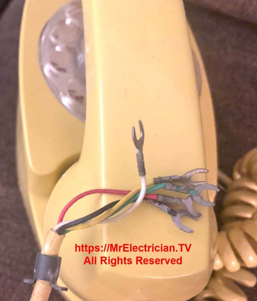
The red and green wires on the princess phone are identical to any other telephone. The white and black wires were used to power the lighted dial.
Click here for a Princess Phone internal wiring diagram.
Here is a service bulletin for Princess Telephones.
Click for an extensive memorial of Bell System Practices (BSPs) in PDF format.
Occasionally, I find an old Western Electric light gray or beige or light gray-colored low-voltage transformer plugged into an electrical outlet in someone’s basement. I recall having one of my regular clients get me over to check their phone wiring after a telephone repair person told them that they had voltage on their telephone wires.
I knew exactly what was causing the voltage on the phone wires. It was the above-mentioned long-forgotten transformer. The original purpose of that transformer was to provide power to a Princess Telephone with a dial that lit up. Those phones are no longer around, but many of their small gray or beige power supply transformers still are. Unplug it if you see one in your house or, more likely, in your basement.
The low voltage wiring to the Princess telephone power transformer was an ordinary CAT 3, two-pair telephone wire. The conductors’ colors are red, green, black, and yellow. I think the yellow and black wires were connected to the terminals on the transformer.

TELEPHONE TOOLS
I don’t advertise to do telephone wiring as I am geared up for electrical work. However, several times when I have been in clients’ homes, I got asked to install one or more telephone jacks. So I bought myself a telephone wire punch-down tool and a tone tracer to identify the correct pair of wires.
The telephone tone tracer is fabulous for tracing telephone wires, but it does not work as well on complicated electrical circuit wiring. Other electrical circuit wire tracers are available, especially for electrical circuit wiring.
I also bought a spool of the satin phone cord to connect the phone to a phone jack, along with some RJ11 plugs. This required a unique tool for assembly. I bought a cheap phone plug crimper to make phone cords any length clients wanted.
For concerns about lightning safety and prevention with phone and cable TV, read my article about grounding TV and telephone.
Click here to see my specialized electrician tools.
Wiring diagrams of mine for bathroom fans, ceiling fans, two-way switches, three-way switches, four-way switches, and motors can be found by clicking here.
To help keep this website FREE, please use this Amazon link for all of your purchases.
Click here to receive a FREE copy of my book “Almost Everything You Need To Know To Repair a Bathroom Exhaust Fan In Your Home.”
Get your required “Emergency Disconnect, Service Disconnect” labels and stickers to satisfy the 2023 National Electrical Code requirements in article 230.85(E)(1) and (2) by going to my Zazzle Shop here.
Visit my Link Tree for social, stickers, and merchandise links.


