Dear Mr. Electrician: How do I install a Wiremold garage ceiling outlet using a surface metal raceway on the ceiling to power my electric garage door opener?
Answer: A Wiremold garage ceiling outlet can easily be installed if an existing electrical outlet is on the garage wall.
An extension box can be added to an existing electrical outlet, and the Wiremold raceway is attached to that and continues up the wall and across the ceiling using the proper fittings.
NOTE: Some text links below go to applicable products on Amazon or eBay. As an Amazon Associate, I earn from qualifying purchases. Using my links helps to keep this website FREE.
A client was selling his house and needed to have an electrical outlet installed for the garage door opener. I added a Wiremold 500 surface metal raceway to an existing wall switch and outlet to power a new ceiling electrical receptacle.
Below are photos of the Wiremold metal surface raceway installation in his garage. It was to replace an extra-long homemade power cord that was tacked to the garage ceiling and wall for the garage door opener.
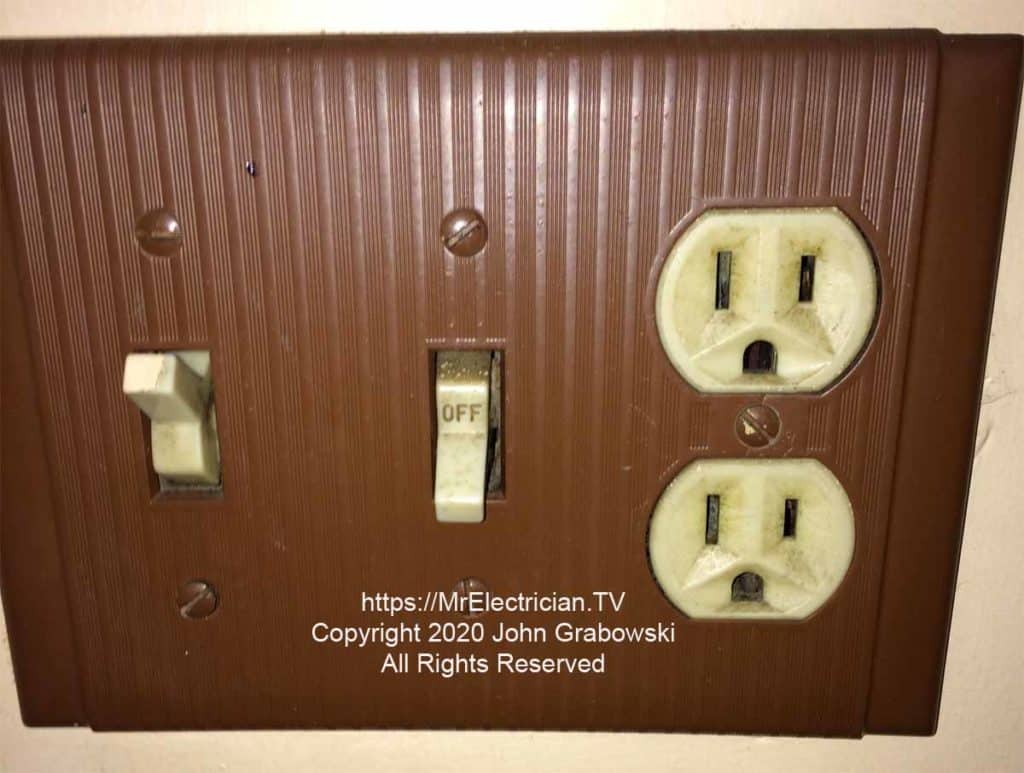
Next to the human entrance door at the rear of this garage, there was an existing three-gang metal switch box in the wall for two switches and one electrical outlet. One of the switches below was a 3-way for the garage light, the other a single pole for an outside light. The existing outlet was not GFCI protected, which is required for garage electrical outlets. See article 210.8(A)(2) in the National Electrical Code (NFPA 70).
Below is the result of the same switch and outlet location after installing Wiremold 500 surface metal raceway for a ceiling electrical receptacle outlet above the garage door opener. The three-gang Wiremold extension box extends less than an inch out beyond the finished wall.
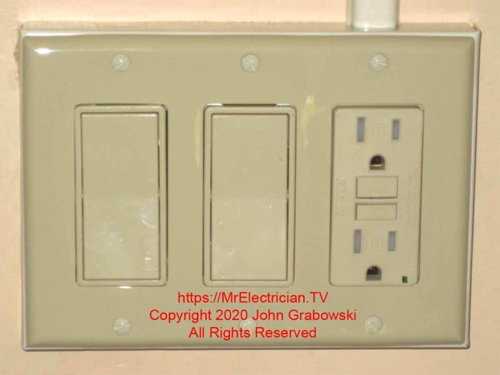
A Wiremold V5751-3 three-gang extension box was used to attach it to the existing electrical box. More photos are below.
ADDING A WIREMOLD GARAGE CEILING OUTLET
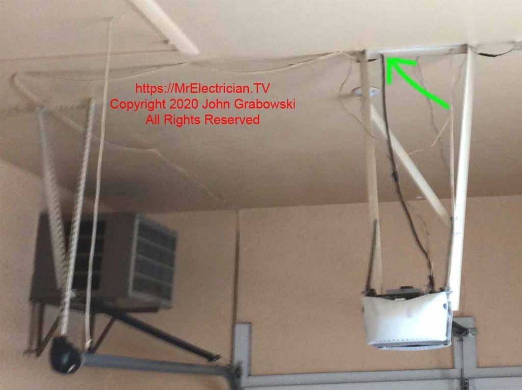
In the above photo, you can see the extra-long power cord (Painted the same color as the ceiling) tacked across the ceiling to an outlet on the inside front wall of the garage. That is not an extension cord, but the cord is wired directly into the garage door opener.
The green arrow points to the hole in the steel the cord passes through. This is unsafe because the steel could cut into the insulation on the wire and cause a short circuit or an arcing condition.
Click Here to See Wiremold 500 Fittings On eBay.
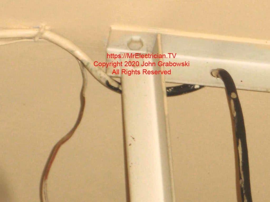
Passing the cord through this steel bracket was not a good idea. Whoever did this removed the factory-installed power cord from the garage door opener and installed their own much longer, homemade power cord.
The user-installed cord was stapled to the ceiling and down the wall to an outlet at the front of the garage. The steel could have cut into the cord and created an electrocution hazard. The electrical outlet was not GFCI or AFCI-protected.
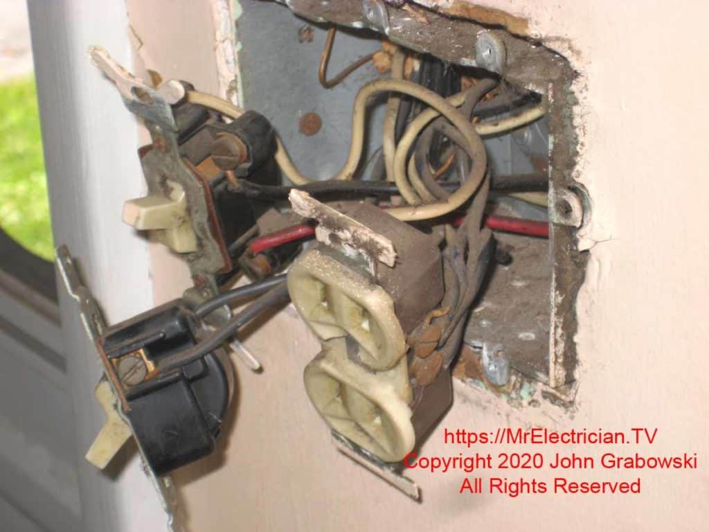
The existing wiring consisted of a three-way switch for the garage light, a single pole switch for an outside light, and an electrical outlet that was not GFCI-protected.
The LINE screw terminals for the new GFCI outlet were connected to the same wires that supplied power to the old outlet. The new Wiremold ceiling outlet wires are connected to the LOAD terminals on the GFCI. The new switches were connected just like the old switches.
I surmise that the rusted screws on the side of the outlet above were a result of these devices being mounted inside of an uninsulated outside wall. There didn’t appear to be any water infiltration.

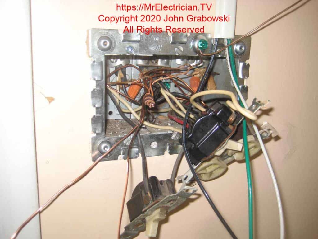
The three gang extension box base ring is attached to the existing wall box using 6/32 screws. After installing the base plate, it is possible to begin the Wiremold installation. The Wiremold 500 slips onto the short tongue on the base plate.
Note the ground wire pigtail under the green screw. It is not easy to see, but it is connected to the bunch of ground wires first, then wraps around the green screw and has enough slack left over to connect to the GFCI.
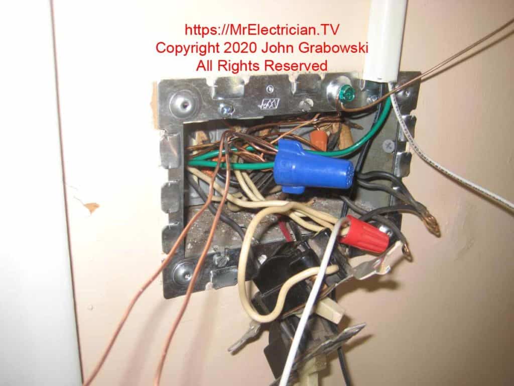
A big blue wire connector was needed to connect all ground wires tightly.
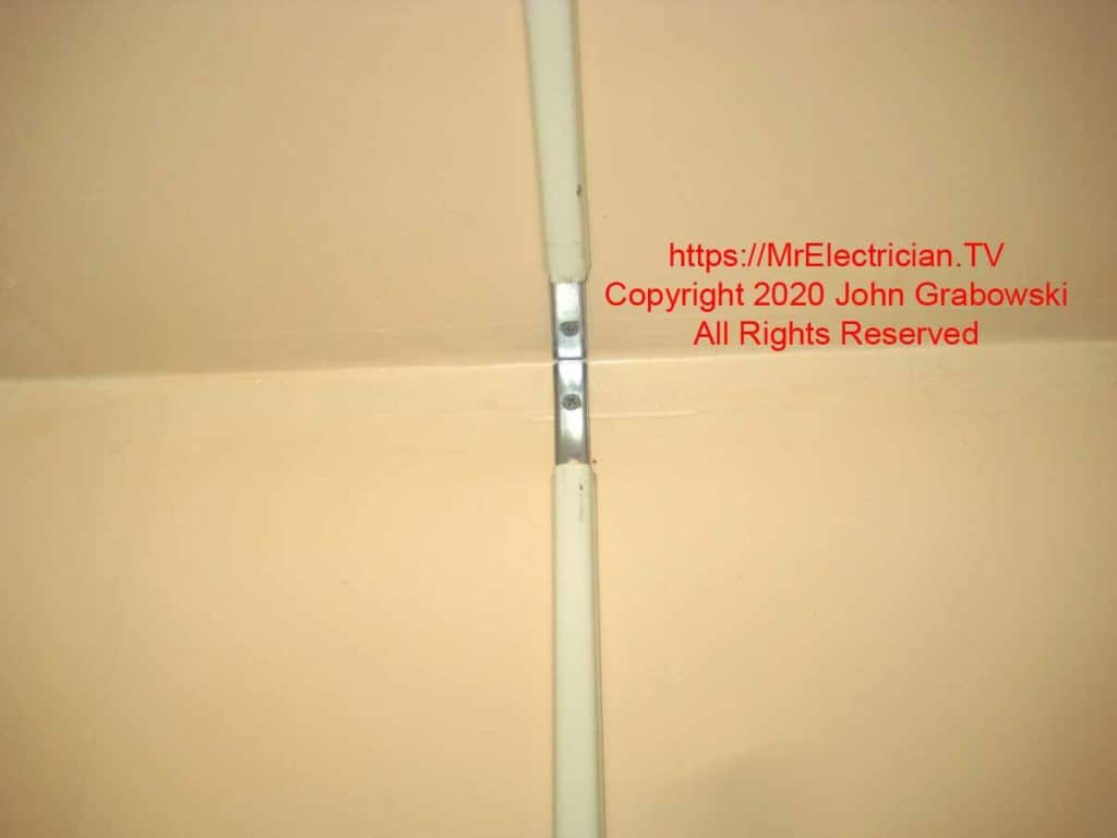
The V517 internal elbow is added to one end of the metal raceway and put into place. After the elbow is secured using deck screws because of their flat head, a piece of 500 raceway can be inserted at the other end.
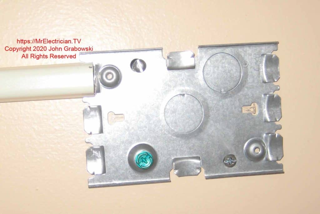
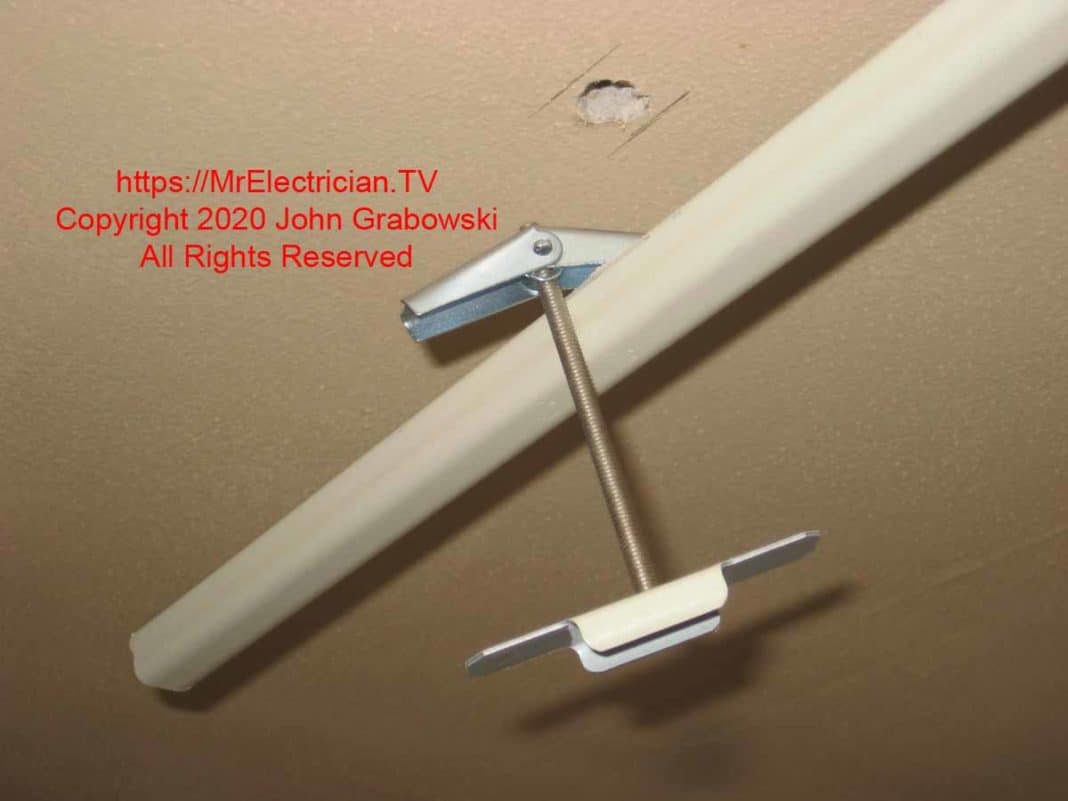
The short tongues on the base above are a good solid connection after being inserted into the Wiremold. The above V5747 outlet box base was attached to the ceiling using two toggle bolts.
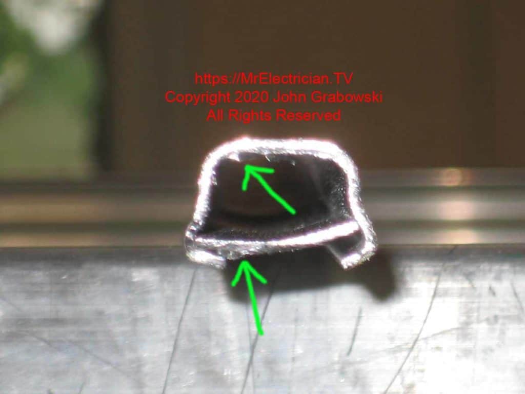
The Wiremold factory recommends cutting #500 using a hack saw with 32 teeth per inch. This will reduce the size of the burrs on the cut pieces. Removing the metal burrs (Indicated by the green arrows above) is essential after cutting Wiremold. The inside burrs can nick the insulation, and the outer burrs can interfere with the Wiremold connecting to a box or fitting.
I use a small half-round file for the inside. A flat file for the outside. I insert a flat screwdriver into the two narrow slots to clean them out.
