Dear Mr. Electrician: How do I install an electrical receptacle box using Madison Bars? I want to install an electrical outlet on a dedicated circuit for my window air conditioner, and someone told me to use electrical Madison Bars to mount the outlet box.
NOTE: Some text links below go to applicable products on Amazon or eBay. As an Amazon Associate, I earn from qualifying purchases. Using my links helps to keep this website FREE.
Answer: Installing an electrical receptacle box using Madison Bars is a simple method for mounting gangable metal electrical boxes with ears in a wall.
Electrical Madison Bars are also known as Old Work Box Mounts, Old Work Support Clips, F Clips, F Straps, Madison Clamps, Jiffy Clips, Hold-It Box Supports, Madison Clips, Madison Straps, and Battleships.
The electrical manufacturer Hubbell Raco calls them GRIP-LOK Old Work Switch Box Supports with 1 7/8″ long legs. The catalog number is 8977.
The manufacturer, Steel City, named them Old-Work Switch Box Steel-Mounting Holder #820D.
The photo above shows Madison Bars, which are two different lengths. The longer ones work on walls with double drywall or a finished surface such as tile or paneling.
Switch box support clips, which can attach metal outlet boxes to the wallboard, are also shown in the photo above. They clip onto the front of the electrical switch box with a little force. Once the box is in the wall, you tighten the screw, and the clips wedge themselves between the box and the inside of the wall. You can also buy electrical switch boxes with built-in switch box support clips.
In the example below, the hole for installing an electrical receptacle box with Madison Bars was made using a Compass saw. The metal outlet box was held against the wall, and a pencil line was traced onto the surface. Note the notches on the upper right and lower left corners. They are to allow for the protruding screws on each side that all gangable metal receptacle boxes of this type have.
The boxes are gangable by removing one or both sides and screwing the boxes together with additional boxes to make a multi-gang switch or outlet box. You can add as many gangs as needed; however, the more gangs, the more difficult it will be to find wall plates to cover the finished work.
You can special order multiple-gang wall plates from an electrical supply company, but you may be limited in choosing colors and styles. I have found it best to limit your gangs to four to find wall plates easily. Over four gangs usually must be specially ordered.
Decora-style switches, outlets, and combination devices have the same style outlet cover, making it much easier to find wall plates. The same wall plates also fit over GFCI electrical receptacle outlets.
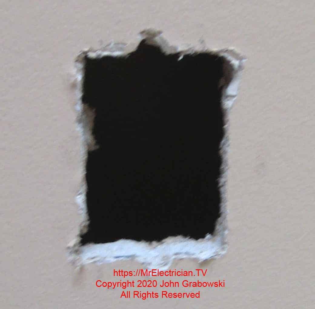
For the hole above, I held the face of the electrical box against the wall and penciled an outline to follow with my Compass Saw.
INSTALLING AN ELECTRICAL OUTLET BOX USING MADISON BARS
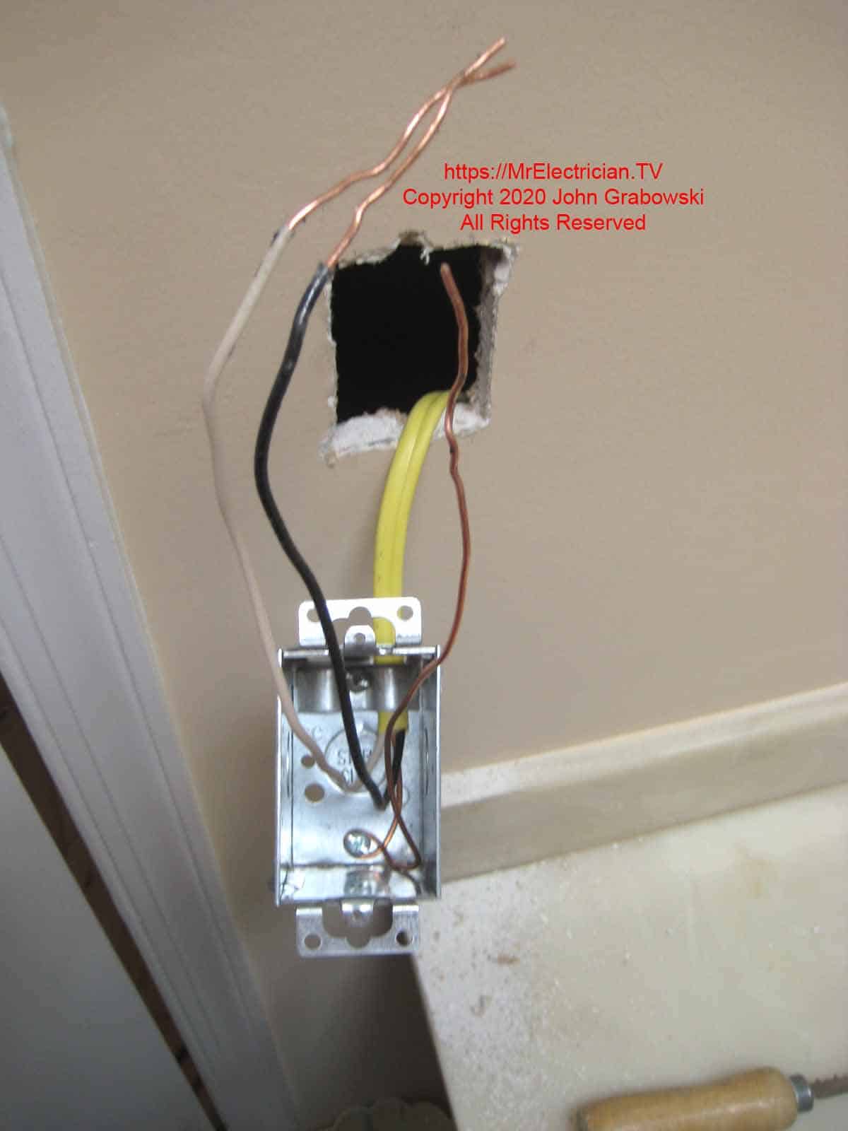
The ground wire above is attached to the box using a separate 10-32 ground screw. Consult Article 314 in the National Electrical Code for the correct size electrical box needed for the number of wires and devices contained within.
It is essential to have the hole cut correctly when installing an electrical outlet box using Madison Bars. If the hole is too big, the ears on the electrical box will not hold against the wall, as the Madison Bars will pull the box inward.
The ideal location for the new outlet box is next to a wood wall stud. In that scenario, I will drill a 3/16″ hole about midway back on the side of the outlet box against the wood stud. After I install the Madison Bars securely, I will screw a #8 x 1 1/4″ sheet metal screw into the wood stud. Do not over-tighten the screw; it will distort the box and make it tilted.
When installing the electrical receptacle box adjacent to a wood stud, it is best to notch the wood stud a little where the protruding screw tab on the box will come in contact with the wood. This is done to keep the box straight; otherwise, the protruding screw tab will cause the box to tilt.
Before buying an oscillating multi-function power tool, I would use a hammer and wood chisel to notch the wood stud. The photo below shows the gap in the wood wall stud in the lower left.
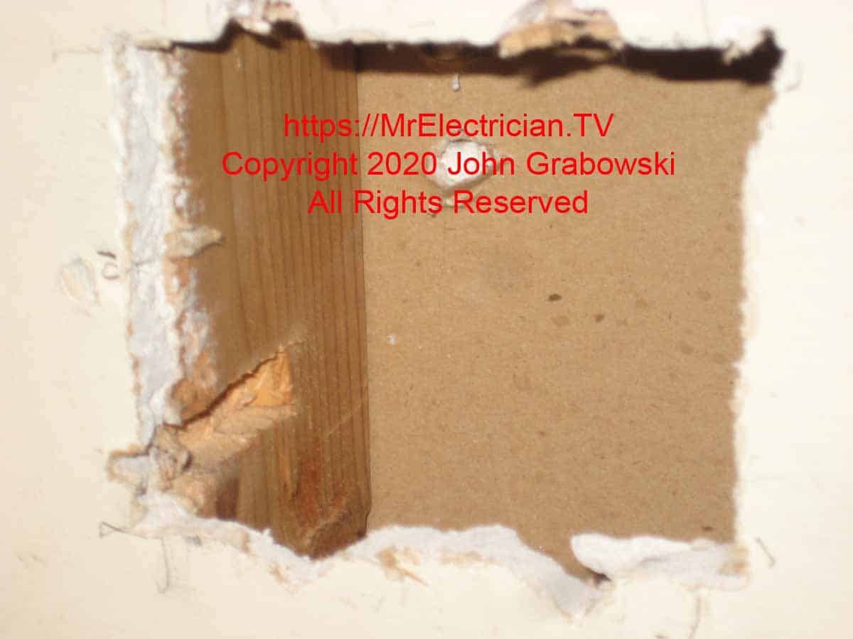
The notch in the wood stud’s lower left section in the photo above accommodates the protruding screw and tab on the gangable box. I used my oscillating multi-function tool to make the notch.
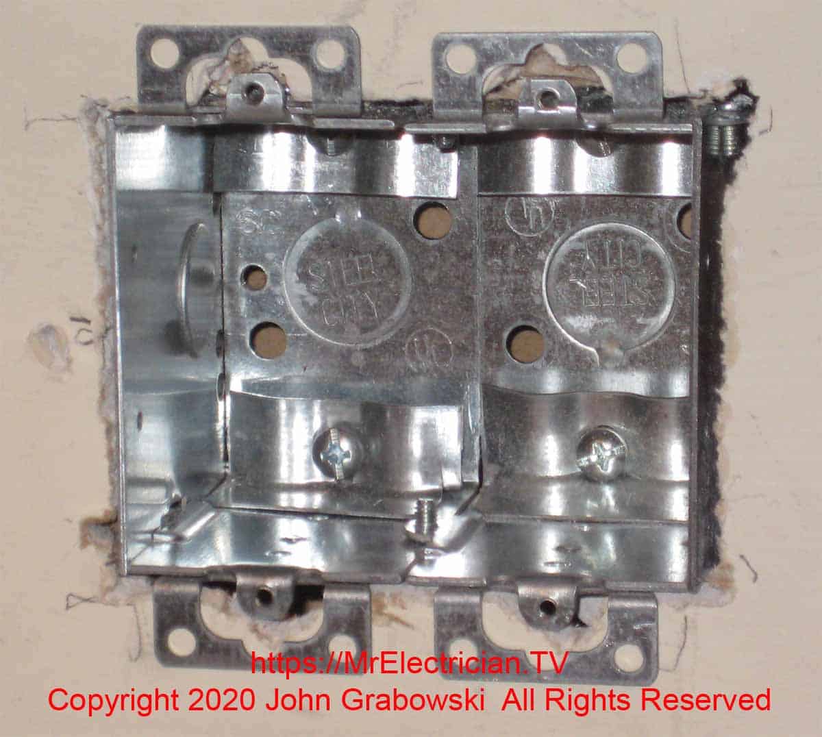
All extra cable clamps must be removed because each one counts as one additional wire when calculating box fill. See article 314.16 and tables 314.16(A) and 314.16(B) in the National Electrical Code.
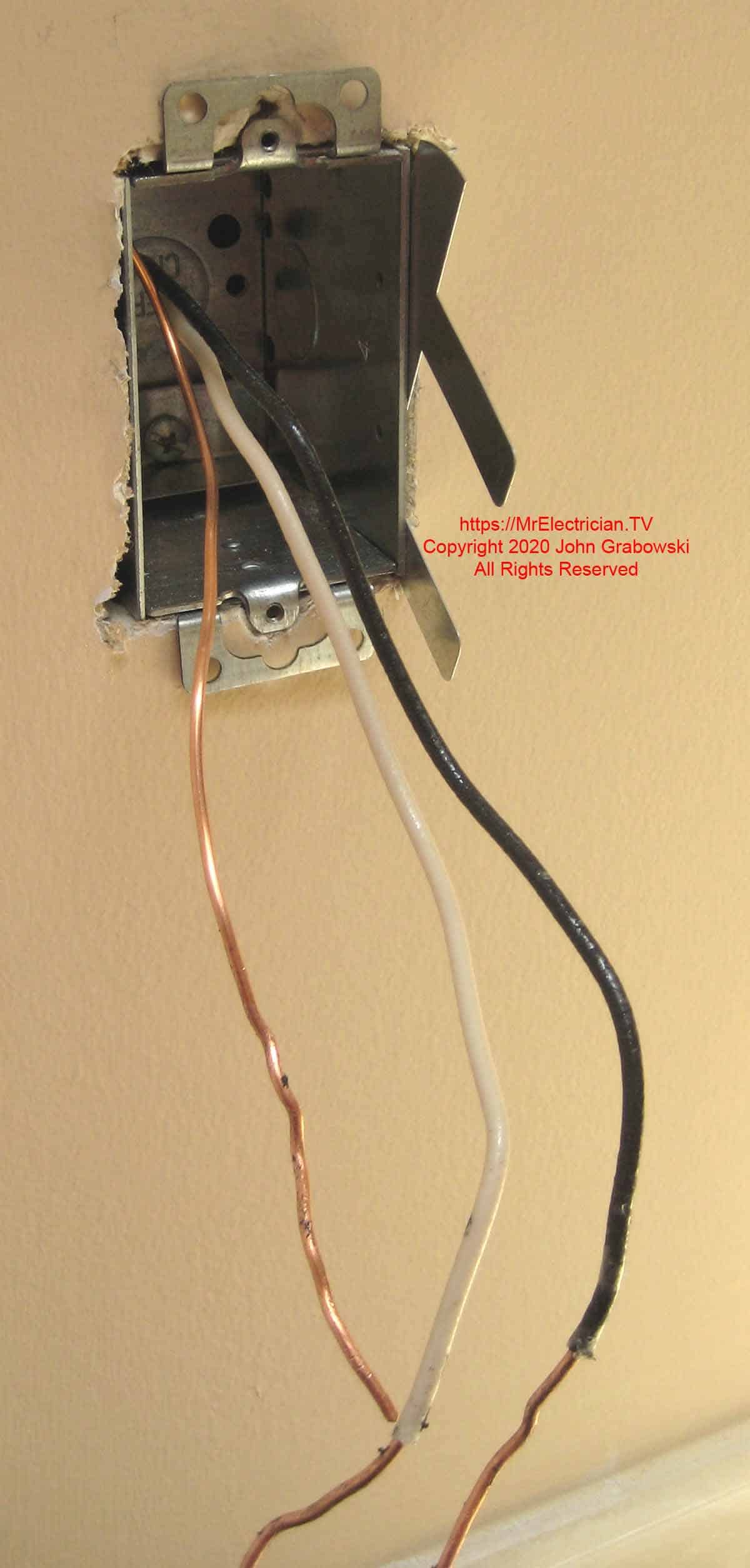
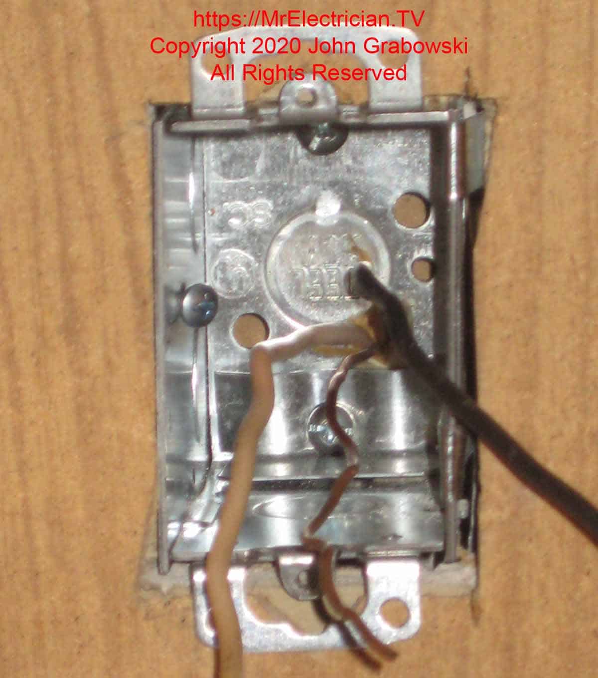
Bring the cable into the electrical box and tighten the clamp enough so that the cable cannot be easily pulled out. Do not over-tighten the clamp, as it could cause an internal short circuit on the cable. Remove the other unused clamp entirely and save the screw for grounding. All extra cable clamps have been removed in the photo below, and one 10/32 machine screw has been inserted for grounding purposes.
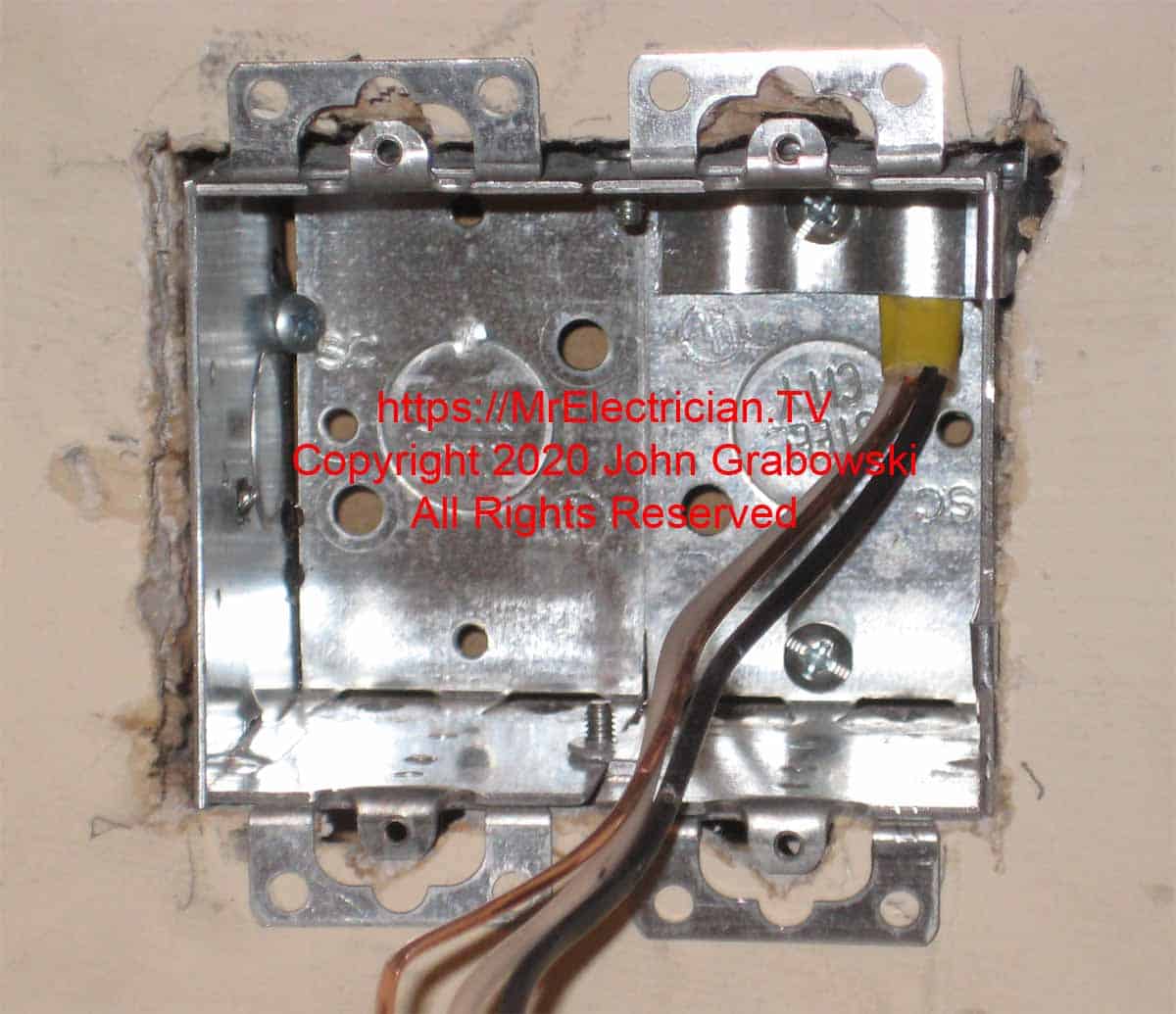
The electrical outlet box in the photo above is attached to the wall with one Madison Bar. The other side is secured with one #8 sheet metal screw through a hole that I drilled. A 10/32 screw for grounding is on the bottom right side.
Wrap a separate grounding pigtail around the unused 10/32 screw to ground the box, which joins with a grounding pigtail for the outlet or switch. You can also use grounding screws.
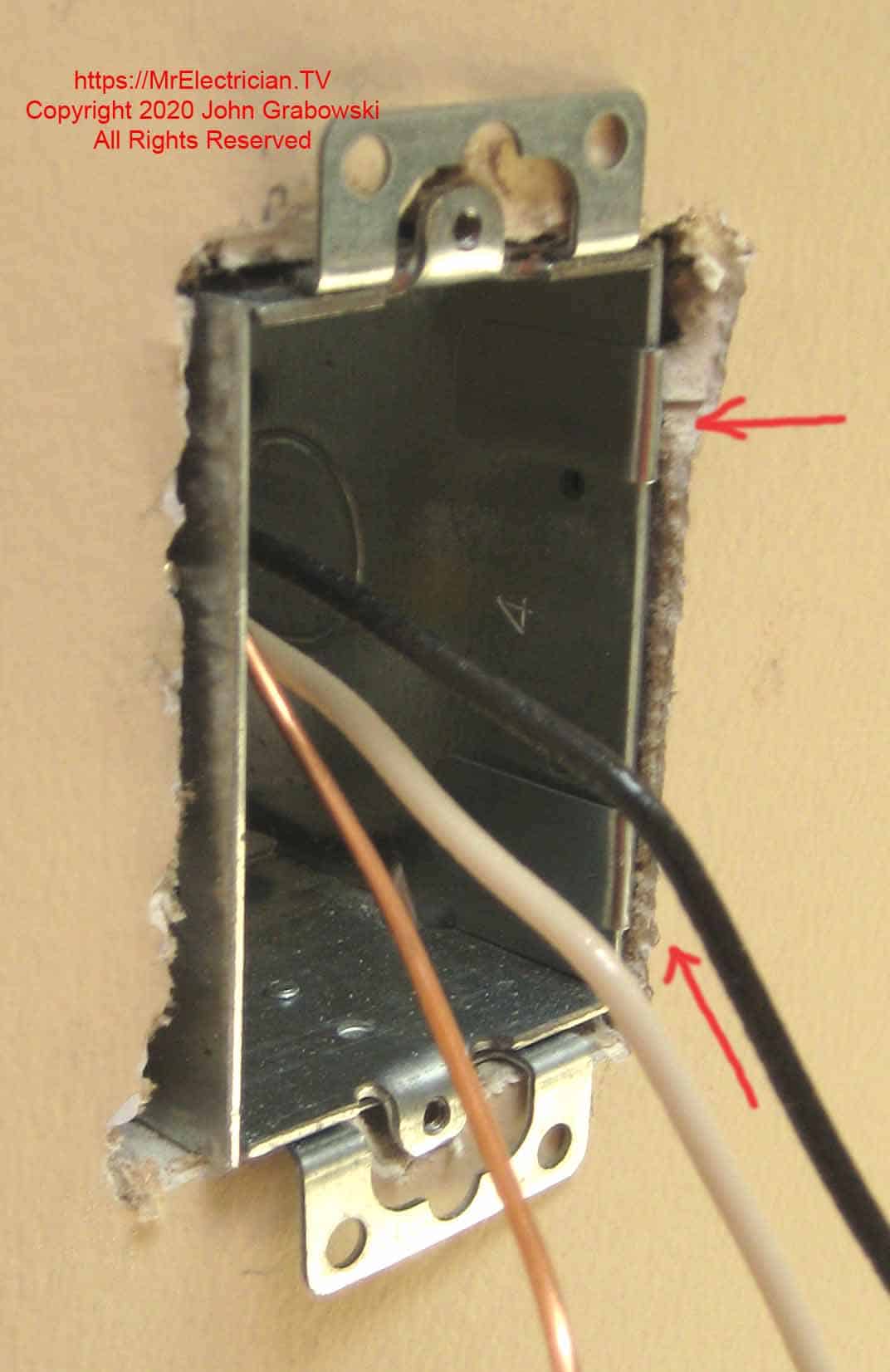
A metal electrical outlet box is in the wall with a suitable Madison Bar bent over. You can push the electrical box into the wall with the cable clamped cable and insert one Madison Bar alongside the box. Slide up the long side so that the short side of the Madison Bar can go into the wall. With the opposite side of the electrical box protruding about 1/4″ – 3/8″, push the box’s side with the Madison Bar into the wall hard using a big flathead screwdriver.
While holding one edge of the box in with the large screwdriver, bend the metal tabs of the Madison Bar inward towards the inside of the box. Squeeze the tabs tightly with long nose pliers.
Having the opposite side of the outlet box protrudes out a little is essential. That will make the Madison Bar on that side very tight and hold the box in the wall more securely.
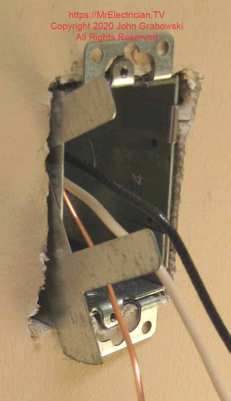
You can use a large flathead screwdriver to push the box against the wall and hold it there; the bigger, the easier. This ensures that the box will be held in place tightly. Use long nose pliers to crimp the Madison Bars tightly against the metal electrical box.
Insert another Madison Bar on the other side of the electrical box with the long end of the Madison Bar pointing in the opposite direction of the first Madison Bar. Push the box with the large flathead screwdriver and bend the metal tabs. Pinch the tabs tightly with needle nose or with long nose pliers.
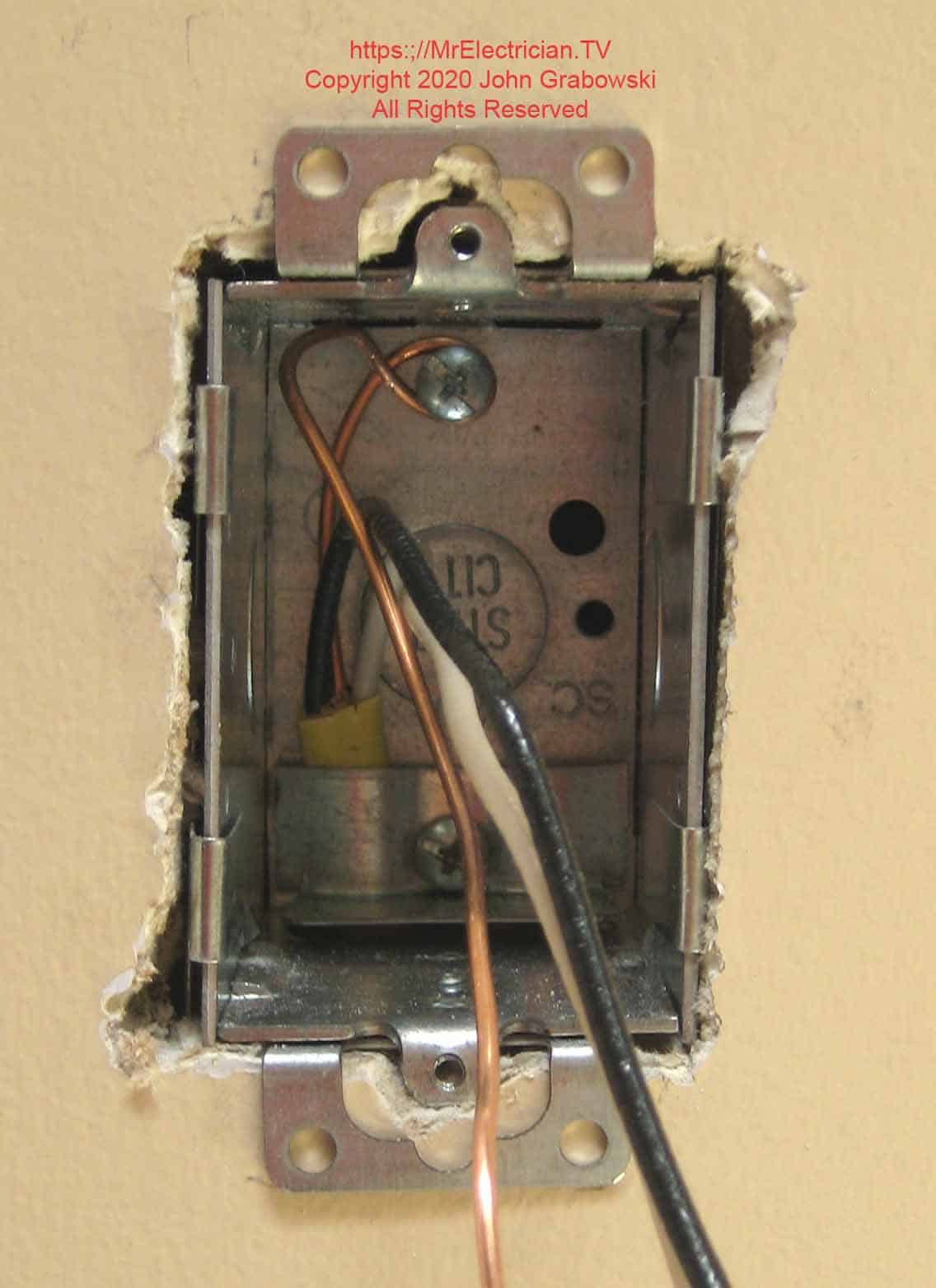
When installing an electrical receptacle box using Madison Bars, the electrical box should be very snug against the wall once the Madison Bars are entirely in place. It should not be loose. Note how the box’s upper and lower screw hole tabs are slightly set back into the wall. Inside the rear of the box is the bare copper ground wire attached to the metal box using a 10/32 screw.
After securing the box, you can adjust it for straightness by lightly tapping it with a screwdriver and your pliers.
UPDATE: Grounding the electrical box above by wrapping the feed cable bare grounding conductor around a 10/32 screw and using the extra length as a pigtail to attach to a wiring device is no longer permitted.
You now must use a separate grounding pigtail to ground the box and then splice all of the ground wires together with an additional pigtail to connect to the green screw of the wiring device. The grounding technique shown in the photo was outlawed in the 2020 National Electrical Code Article 250.148(C).
See my blog post about grounding outlets and switches for information on proper grounding methods.
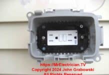
Remove the ears when installing a wiring device such as a switch or electrical receptacle outlet onto a gangable metal box with its ears on the wall surface. The wall plate will fit better against the wall. In the image below, I removed the ears after I took the photo of the GFCI receptacle.
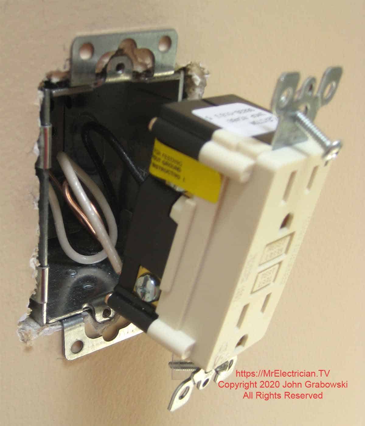
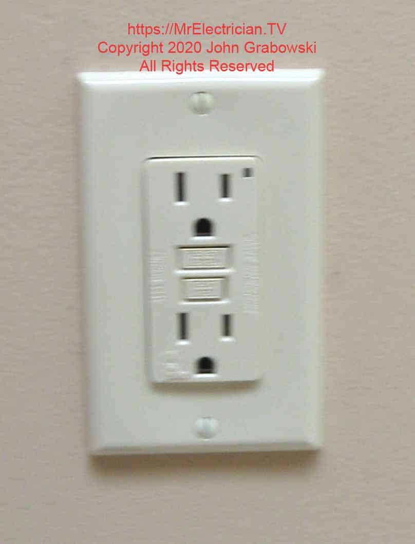
I prefer to install the old work electrical box next to a wall stud so that a wood or sheet metal screw can be screwed through a hole in the box directly into the wood stud in addition to the Madison Bars. That makes the box extremely secure. However, on this job, the client wanted the receptacle installed in the exact location above.
The photo below shows the wiring devices with the ears removed so that they sit closer to the wall. The copper-colored clip on the bottom of the GFCI outlet is for self-grounding. This means the outlet is grounded through the screw, and no additional grounding conductor is necessary. However, I still connect the grounding conductor to the outlet to ensure a good grounding connection.
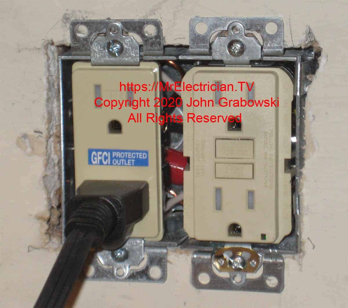
The ears on the outlets above have been removed so that the outlets sit better on the electrical box. A cord is plugged into the GFCI-protected outlet.
The Madison Bars work best with at least 1/2″ thick or thicker drywall. I sometimes had a problem using Madison Bars on 3/8″ drywall. Mounting a new box next to a wall stud is always best. That gives you something to screw on to in case the Madison Bars don’t hold well. I often drive one #8 sheet metal screw through the side of the electrical box to keep it secure.
The image below depicts a metal outlet box with a Madison Bar on the right and a #8 sheet metal screw on the left. Sometimes, I don’t need two Madison Bars.
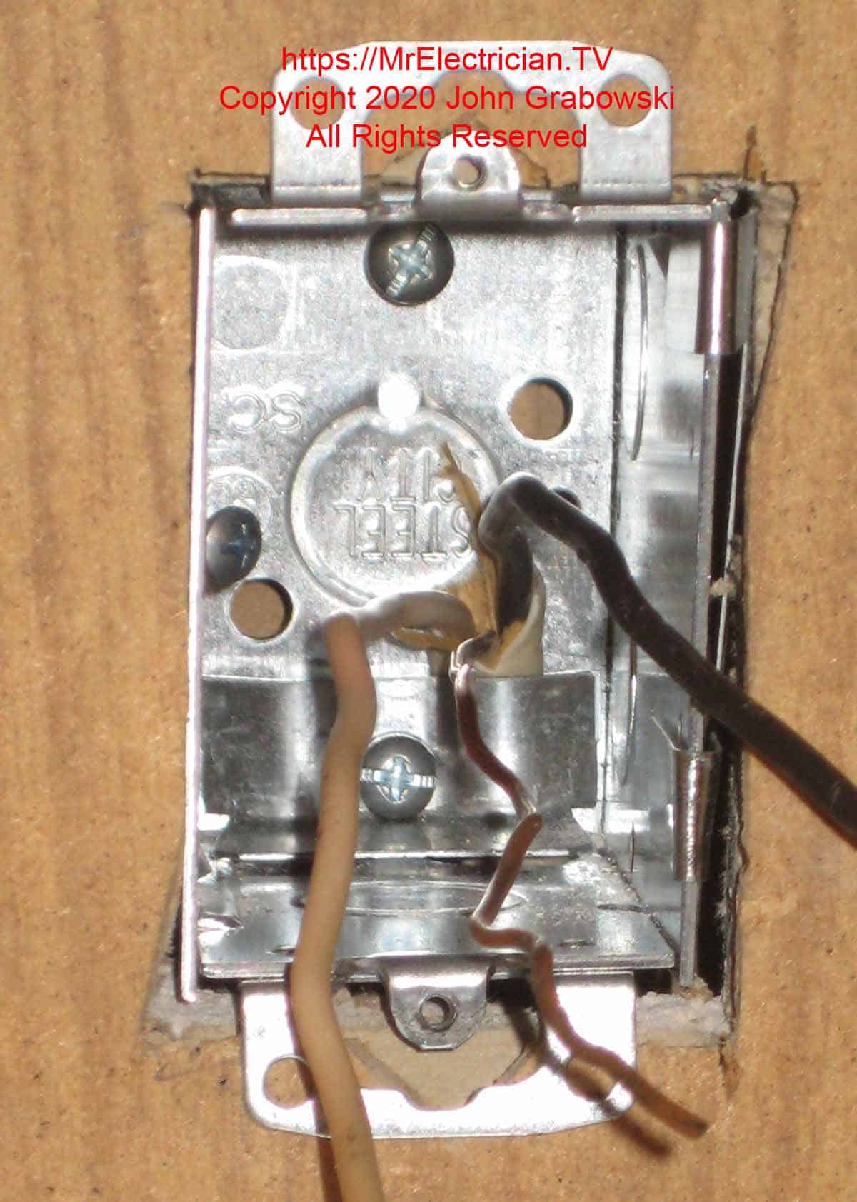
You can see in the above photo the 12/2 Type NM cable is entering from the bottom under the cable clamp. The upper cable clamp has been removed, and the clamp screw has been reinstalled for grounding the box. Always remove the unused clamps before grounding to the screw. Unused clamps should be removed as they contribute to the conductor box fill.
Below is the #8 sheet metal screw on the left going into a wood stud. The screw must be set back enough so the screw head does not contact the receptacle. I usually drill the hole in the middle of the side on a 3.5″ deep gangable outlet box before installing the box in the wall. When drilling, after penetration, I slowly work the drill bit at the angle that the screw will be entering.
Click here for my post about installing an electrical receptacle in an existing wall. It will be helpful.
This post demonstrates adding an electrical box to a narrow space from behind.
The Hubbell Raco catalog page for their GRIP-LOK old work switch box supports is here.
To help keep this website free, please use this Amazon link for your purchases. As an Amazon Associate, I earn from qualifying purchases.
Click here for a FREE copy of my book “Almost Everything You Need To Know To Repair a Bathroom Exhaust Fan In Your Home.”
Get your required “Emergency Disconnect, Service Disconnect” labels and stickers to satisfy the 2023 National Electrical Code requirements in article 230.85(E)(1) and (2) by going to my Redbubble Shop here.
Visit my Link Tree for my social media connections.

