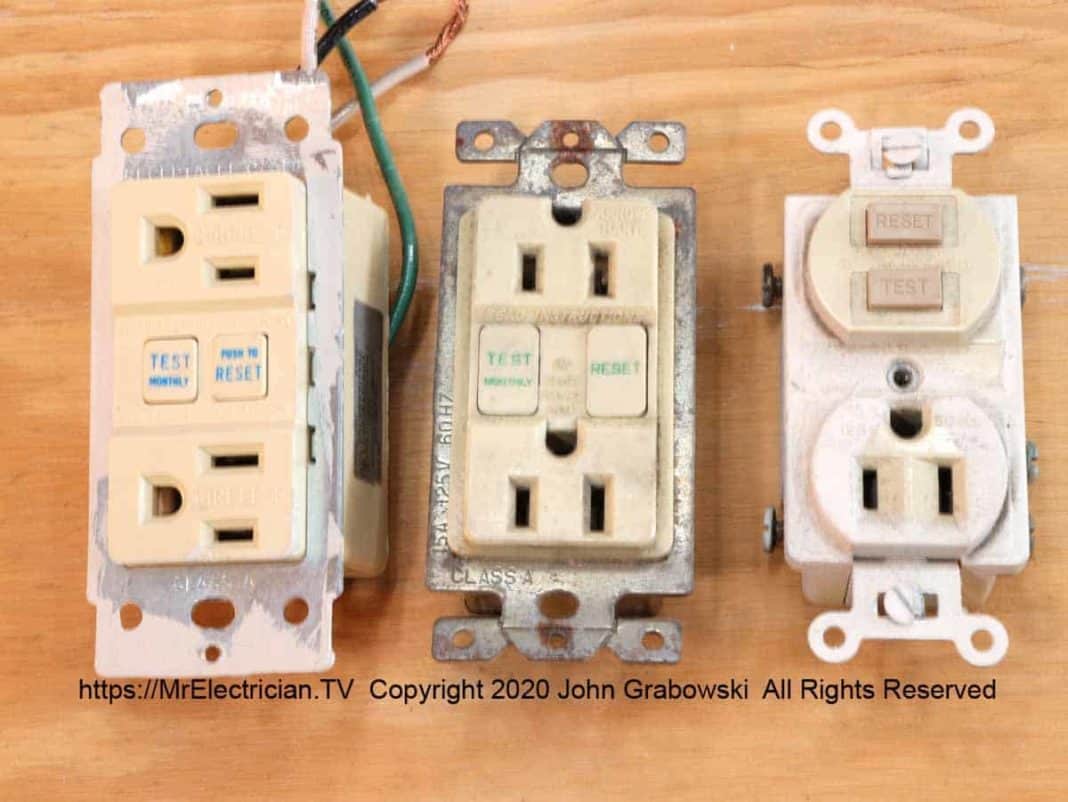
Dear Mr. Electrician: How do I replace a GFCI electrical receptacle? I occasionally push the “Test” button on my bathroom GFCI (Ground fault circuit interrupter) receptacle, but nothing seems to happen. How do I know if the GFCI receptacle is working correctly?
Answer: By pushing the “Test” button, a simulated ground fault of approximately five milliamperes is shorted across the internal conductors and should cause the GFCI (Ground fault circuit interrupter) receptacle to stop working immediately. Typically, you hear a gentle click sound, and the “Reset” button might pop out a little.
Table of Contents:
NOTE: Some text links below go to applicable products on Amazon. As an Amazon Associate, I earn from qualifying purchases. Using my links helps to keep this website FREE.
TESTING A GFCI ELECTRICAL RECEPTACLE
Suppose the GFCI is not deactivated after pushing the “Test” button. The GFCI receptacle should be replaced immediately because you are no longer protected against an electric shock or electrocution.
Pushing the “Reset” button should reactivate the GFCI receptacle. I have found that some “Reset” buttons must be firmly pressed using a blunt tool such as a screwdriver.
Another method that I use to test a ground fault circuit interrupter receptacle is my Ideal Voltage Tester. I put one prong from the voltage tester into the ground pin opening and the other prong into the neutral side of the receptacle, which should always be the larger slot. That usually trips the GFCI if it is working correctly. If it doesn’t trip, replacement is called for.
Tamper-resistant receptacles prevent me from testing this way, so instead, I use my plug-in tester on TR-type receptacles.
REPLACING A GFCI OUTLET
To replace the ground fault interrupter receptacle, you should begin by shutting off the power to that particular circuit at the main circuit breaker or fuse panel. Test the receptacle with a lamp, radio, or an electrical tester to ensure the GFCI receptacle lacks power. This may not be effective as it is possible that a non-working GFCI receptacle may not have power available, regardless.
Therefore you should proceed to the next step with caution and test the actual wires at the screw terminals of the GFCI receptacle using a voltage tester with wire leads, a voltmeter, or a pigtail light socket with a lightbulb.
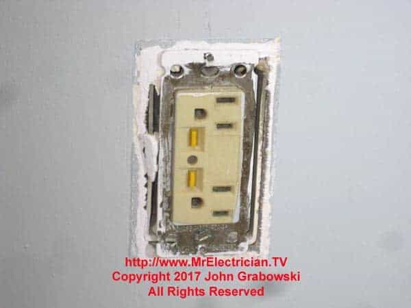
Remove the GFCI receptacle cover by unscrewing (Counterclockwise) the upper and lower screws on the cover plate. Next, unscrew the upper and lower screws that secure the receptacle to the wall-mounted electrical box. Carefully pull the GFCI receptacle straight out of the box as far as it will go. Please take note of the wires connected to it.
Look at the new Tamper-resistant GFCI Receptacle you will use to replace the old one. On the back, you will see some words stamped into it. “LINE” and “LOAD” are what you need to take notice of. Look at the back of the existing GFCI receptacle and note which wires are on the “LINE” and “LOAD” terminals.
In the photo below, the LOAD terminals on this particular brand of GFCI receptacle are taped over from the factory for easy identification. Notice where it says “Hot Wire” on one side and “White Wire” on the other. GFCI receptacles will only work if they are correctly wired.
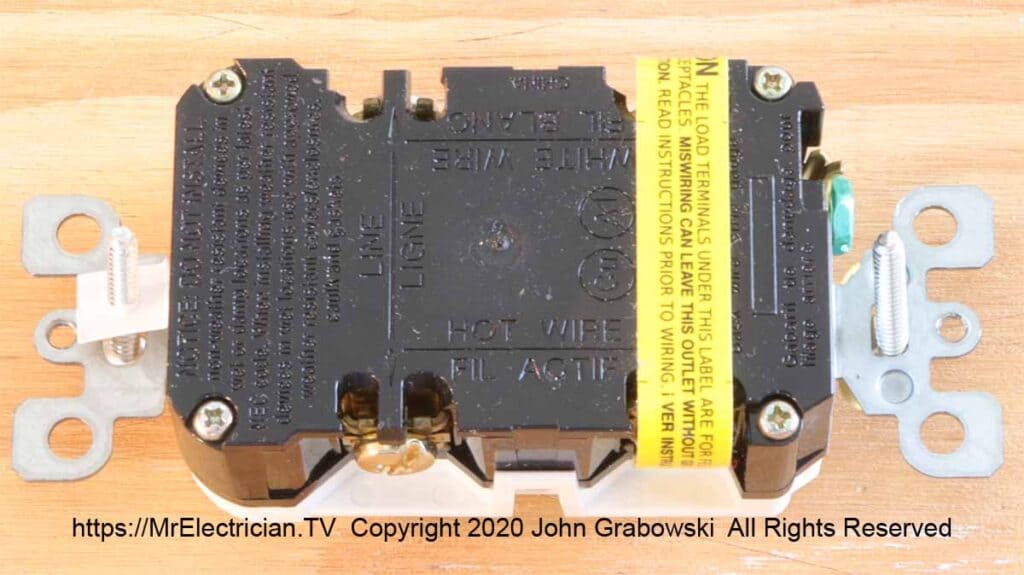
Usually, the wires are white and black. Black on the “LINE” side would be the hot wire that feeds into the receptacle. The white wire on the “LINE” side is the neutral conductor that provides a path for the return current from the black wire.
Remove one wire from the existing receptacle and screw it onto the same terminal on the new GFCI receptacle. Repeat this for each wire until complete. Doing it this way ensures that the new GFCI receptacle is wired the same as the old one. The green or bare wire gets connected under the green screw.
Only one wire goes under the green screw. If there are multiple ground wires in the electrical box, they must be spliced together with a pigtail. Click here to read my blog post about grounding an outlet.
It is possible that the old GFCI receptacle did not have screw terminals for the connections but instead had pigtails that were spliced to the wires in the electrical box using twist-on wire connectors.
You can untwist the wire connectors by turning them counterclockwise and separating the pigtail from each conductor in the box. Do this one at a time and put the conductor on the same terminal as it was connected to on the old GFCI receptacle.
You may find that when you go to replace the GFCI receptacle, the wires coming out of the electrical box are a little short to connect comfortably to the new GFCI receptacle. You should have a minimum of 3″ of wire extending past the edge of the electrical box. If the wires are too short, you can splice short pieces of wire onto them.
Use wires of the same gauge (Usually #14 or #12 solid or stranded). Strip the ends back approximately 1″ and hold them together to cross each other to form a narrow X. Pliers twist the wires together tightly in a clockwise direction.
Trim the end slightly with wire cutters to expose 1/2″ to 3/4″ of bare twisted wire. Use a medium size twist-on wire connectors to complete the splice. Twist the wire connector tightly by hand in a clockwise direction. Repeat this process for all of the short wires in the electrical box.
If the existing wires are too short to work with, I have found that using push-in wire connectors will work. I will first put my pigtail on the push-in wire connector, bend the wire out of the way, and then push the connector onto the short wire. No bare wire should be sticking out from the wire connector. If there is some bare copper wire showing, wrap some electrical tape around it.
Begin the process of putting the new GFCI receptacle into the box by pushing the wires back into the box accordion style, meaning that they are folded and bent in such a way as to compress back into the box as the GFCI is pushed in. Push the GFCI receptacle in enough to catch a few threads for each screw. Be sure that the GFCI is straight and flat.
Use your screwdriver and push the GFCI support strap that holds the screw into the box at the lower and upper points. This will make it easier to turn the screws down. Tighten the screws down but not snug.
Check again to make sure that the GFCI is straight. If it isn’t, now is the time to tap the support strap gently with your screwdriver to the left or to the right to make it look level. There is room in the screw slot to allow for some alignment.
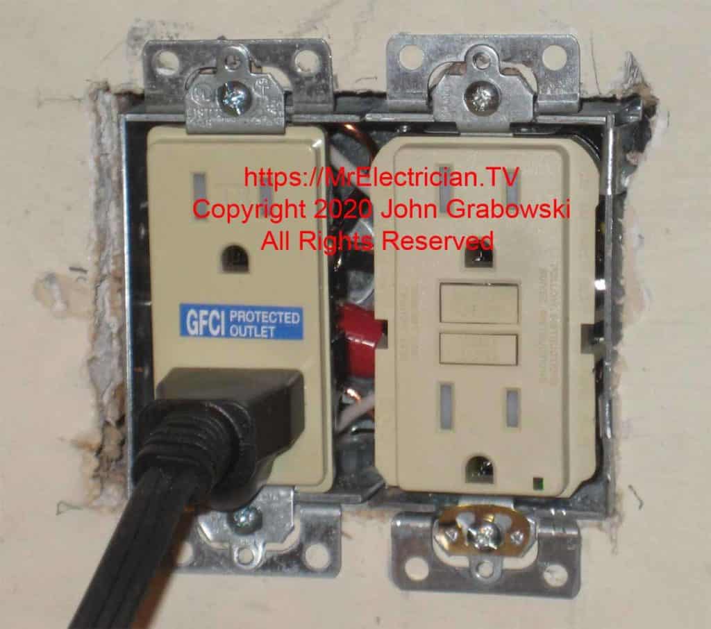
The ears on the outlets above have been removed to seat better on the electrical box.
When the GFCI receptacle is straight, snug the mounting screws down and put the wall plate on. Push the “Reset” button and then the “Test” button to ensure the device operates properly. Some GFCI receptacles are more challenging to reset than others.
I have sometimes used a screwdriver and extra force to push the reset button enough to reset. You can use a plug-in receptacle tester to check for proper polarity.
If a GFCI electrical receptacle is wired to protect other electrical receptacle outlets downstream, the other outlets must be labeled GFCI Protected. These labels typically come within a GFCI receptacle outlet package. That is how I replaced a GFCI electrical receptacle.
In the 2020 National Electrical Code, the requirement for ground fault circuit interrupter (GFCI) protection has been expanded and now includes electrical outlets up to 50 amps at 240 volts. See article 210.8.
If you are replacing or installing a GFCI receptacle in a very old home, you may find my post on replacing two wire non-grounded receptacles helpful.
To help keep this website free, please use this Amazon link for your purchases. As an Amazon Associate, I earn from qualifying purchases.
Click here for a FREE copy of my book “Almost Everything You Need To Know To Repair a Bathroom Exhaust Fan In Your Home.”
Get your required “Emergency Disconnect, Service Disconnect” labels and stickers to satisfy the 2023 National Electrical Code requirements in article 230.85(E)(1) and (2) by going to my Redbubble Shop here.
Visit my Link Tree for my social media connections and links to merchandise in my Redbubble Shop.
