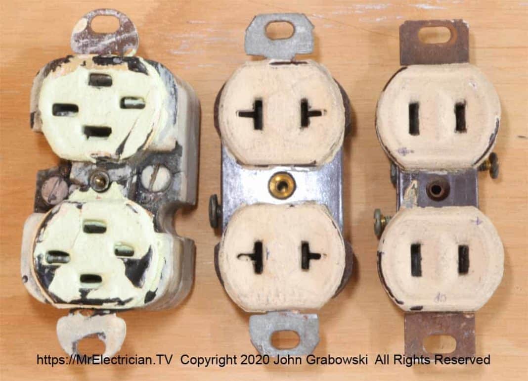
Dear Mr. Electrician: What do I need to do to ground a two-prong outlet? I want to replace the two-prong outlet with a three-prong outlet.
Answer: To ground a two-prong outlet and replace it with a three-prong, you must determine your options. Sometimes it is just a matter of changing a two-prong outlet to a new self-grounding three-prong outlet.
NOTE: Some text links below go to applicable products on Amazon. As an Amazon Associate, I earn from qualifying purchases. Using my links helps to keep this website FREE.
Table of Contents
- DOES MY TWO-PRONG OUTLET HAVE A GROUND?
- TESTING AN OUTLET FOR AN EARTH CONNECTION
- STEPS TO REPLACE AN OLD OUTLET
- WHEN THERE IS NO GROUND AT THE ELECTRICAL RECEPTACLE
- INSTALL A REPLACEMENT FOR AN UNGROUNDED OUTLET
- ANOTHER EXAMPLE OF AN UNGROUNDED OUTLET REPLACEMENT
DOES MY OUTLET HAVE A GROUND?
The BIG question is whether or not you have an approved grounding conductor in the existing outlet box, which would allow you to ground a 3-prong outlet.
Approved grounding conductors can be a separate wire specifically for grounding purposes, metal conduit, the metal armor of type AC cable (BX), short lengths of flexible metal conduit (FMC), short lengths of sealtight (LFMC), metal enclosures, cable trays, and metal raceways including Wiremold metal raceway. See articles 250.62, 250.70, 250.109, and 250.118 in the National Electrical Code (NFPA 70).
Some MC cable metal armor may be approved as a grounding conductor, but you would need to check the labeling on the cable to confirm. Article 250.118(10). Even if the MC cable armor is not an approved grounding conductor, the metal armor must still be grounded using approved MC connectors.
If you have an old house with two prong receptacles, it could have been initially wired by one of several wiring methods available at the time. Knob and tube wiring has no grounding conductor. With proper fittings, BX cable has grounding through its metal armor. Metal conduit is grounded if it is installed correctly.
Non-metallic cable (NM), before it was called Romex, was made with and without a grounding conductor. If it has a grounding conductor, it is most likely smaller than the other conductors in the cable.
TESTING AN OUTLET FOR AN EARTH CONNECTION
You can quickly check for a ground with a voltage tester before you remove the old outlet. Put one lead of the voltage tester on the metal screw for the wall plate. Make sure there is no paint on the screw. Check for voltage by putting the other lead in one of the slots in the outlet. Then put it in the other slot. The smaller slot should be the live one, and the bigger one should be the neutral one.
If one of those connections indicates power, you probably have a grounded connection to the box. You can also use a pigtail light bulb socket for this simple test.
If the test indicates that you do not have a ground connection at the electrical receptacle outlet’s location, see below to ground a two-prong outlet by adding a grounding wire or using Ground Fault Circuit Interrupter receptacle outlets (GFCIs) as a replacement.
STEPS TO REPLACE AN OLD OUTLET
To replace the two-prong electrical receptacle outlet with a three-prong model, turn off the power to this circuit at the circuit breaker panel. Use a voltage tester to confirm the power is off and double-check at each step.
Treat the wires as though they were still alive with electricity when working on them. Just because the circuit breaker is turned off does not mean you cannot get an electrical shock, particularly through the neutral wire. I suggest putting some electrical tape on the bare ends until you can attach them to a new three-prong outlet.
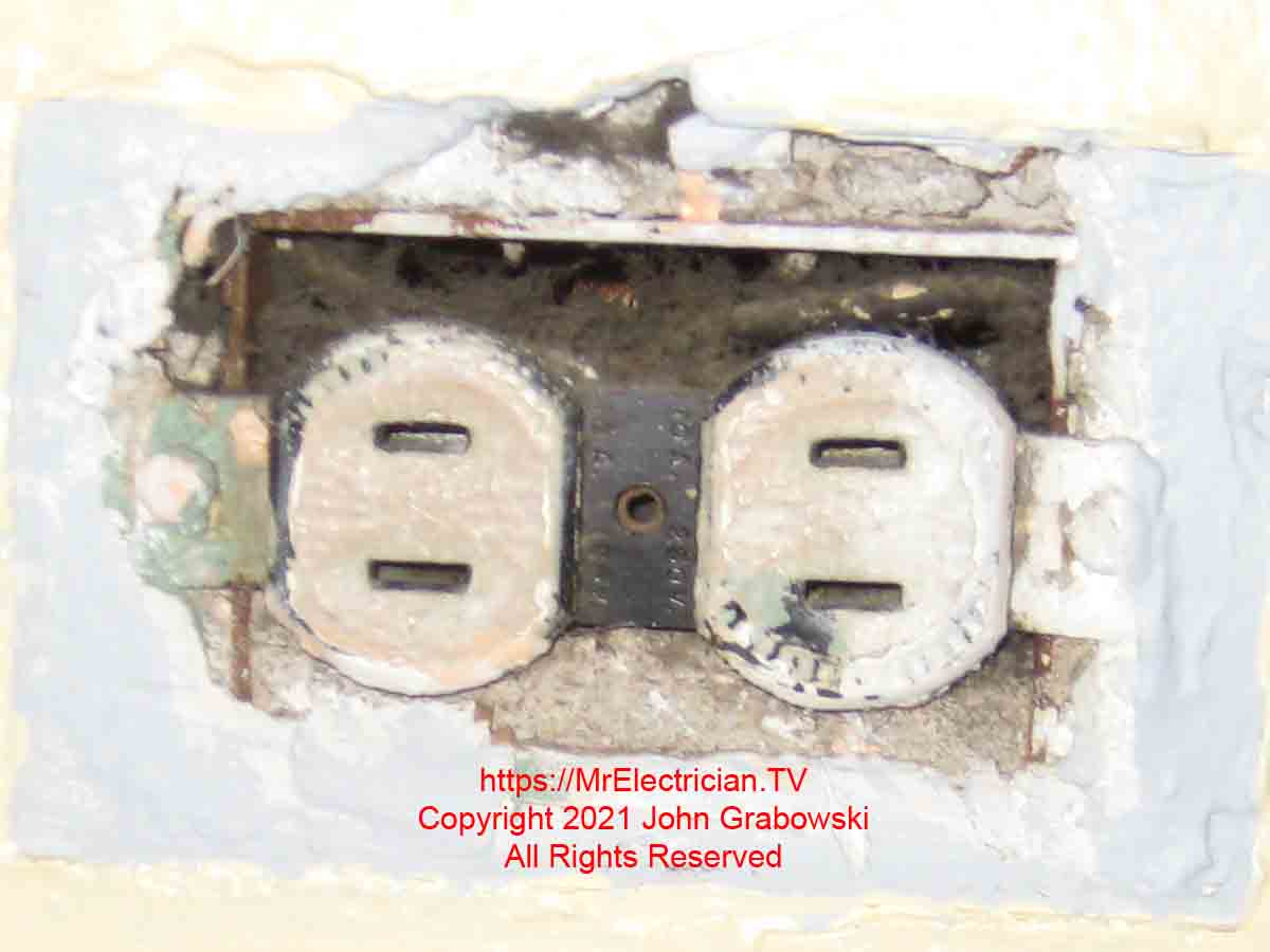
You must take apart the receptacle by removing the wall plate first. Unscrew the center screw (Or upper and lower screws) counter-clockwise. Pry away the wall plate from the two-prong receptacle. The wall plate may be held onto the wall and/or the receptacle by many coats of paint.
Use a razor knife to score along the outer edges of the wall plate. Also, score along the outer face of the receptacle. If the wall plate does not loosen from the knife, try getting a small flat putty knife behind it. In some cases, you may have to break off the wall plate, but the face of the receptacle may come off too. Do this with the power off.
Some newer-style wall plates have the screws hidden. You must pry away the front of the wall plate using a small flat screwdriver. Pry gently and evenly from all corners.
Remove the two screws securing the receptacle to the wall box and gently pull the receptacle away from the wall. If the screws break off, you might be able to grab them with a pair of Vise-Grip Pliers and slowly turn them out.
If that doesn’t work, you may have to drill out the old screw, re-tap the hole for 6-32 or the next bigger size 8-32, and then install a new flathead screw.
I used my razor knife to clean the slots on the 6/32 screws that held the above outlet in the metal outlet box for many years.
The standard receptacle screw thread is 6/32. It is a number 6 machine screw with 32 threads per inch. The screw head is usually a flat head or a low-profile round head. If necessary, re-tap the hole to 8/32 and use an 8/32 flathead machine screw. Use my drill, tap, and screw chart here.
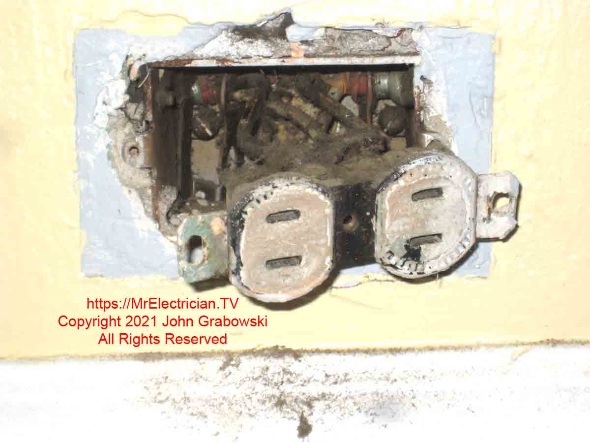
Pull the old two-prong receptacle outlet away from the electrical box. The wires are supposed to be long enough that you can easily work on the receptacle. Quite often, though, the wires are too short, the insulation is old and brittle, and sometimes you have both together. Not to panic, but care must be taken to minimize damage to the insulation. If the wiring is pre-World War 2, it may be soldered and taped.
If you need to make changes or splices, use a sharp knife to cut back any old electrical tape. Do not cut the wires. They are all that you have to work with. Identify all of the wires before taking them apart. Use white electrical tape for the white neutral wires. Use red for switch legs, the wires controlled by a switch. Use black tape for the hot wires.
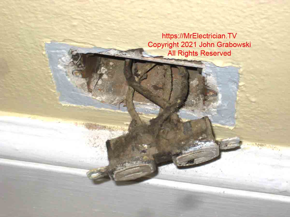
Check the wiring for polarity with a two-wire lead voltage tester or volt meter. Turn the power on and be very careful. It is a good idea to wear insulated electrical gloves when testing live circuits.
With one tester lead held against the metal box, put the other on each of the wires to see which one shows the live voltage. The one that is hot or LINE wire should be wrapped with black electrical tape if the color isn’t obvious or the insulation is brittle.
Now check the black hot wire with one lead and then touch the other lead onto the other wires until you get a reading on your tester. That wire is the neutral conductor and should be identified with white electrical tape. Shut the power off before returning to work to replace the two-prong outlet.
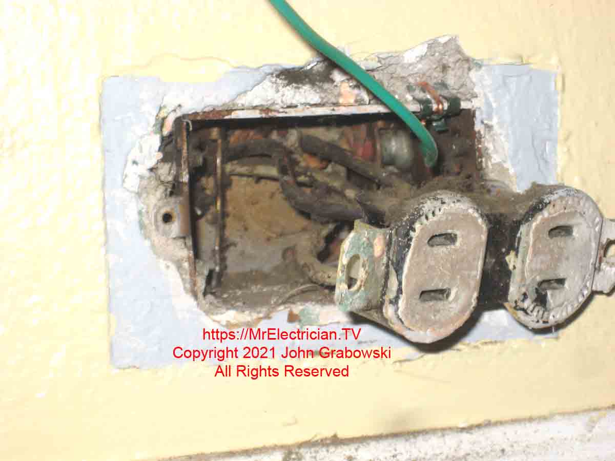
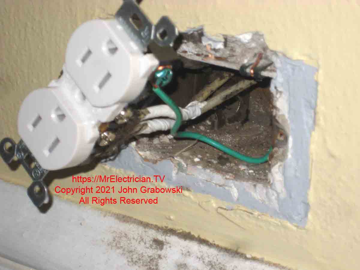
The above photo shows an ungrounded electrical outlet with a grounding pigtail wire attached to the metal box with a grounding clip. After removing all the taped-on insulation, you will see the soldered wires twisted together.
Using a pair of pliers, slowly untwist the wires. The old solder has a very high lead content, making it very soft. Straighten them out and tape them with several layers of electrical tape using the appropriate colors.
If the wires attached to the existing two-prong receptacle are in good condition and the color coding is easily seen, you can remove them. Do not cut them. Loosen the screw or insert a paper clip or small screwdriver into the rear quick-stab clips to release the wire from the receptacle.
If the wires are too short, you can use wire connectors to splice short pieces of wire called pigtails to connect them to the receptacle. Pig-tailing is a good wiring method to use when wiring electrical outlets because the receptacle will never carry the full load of the circuit this way.
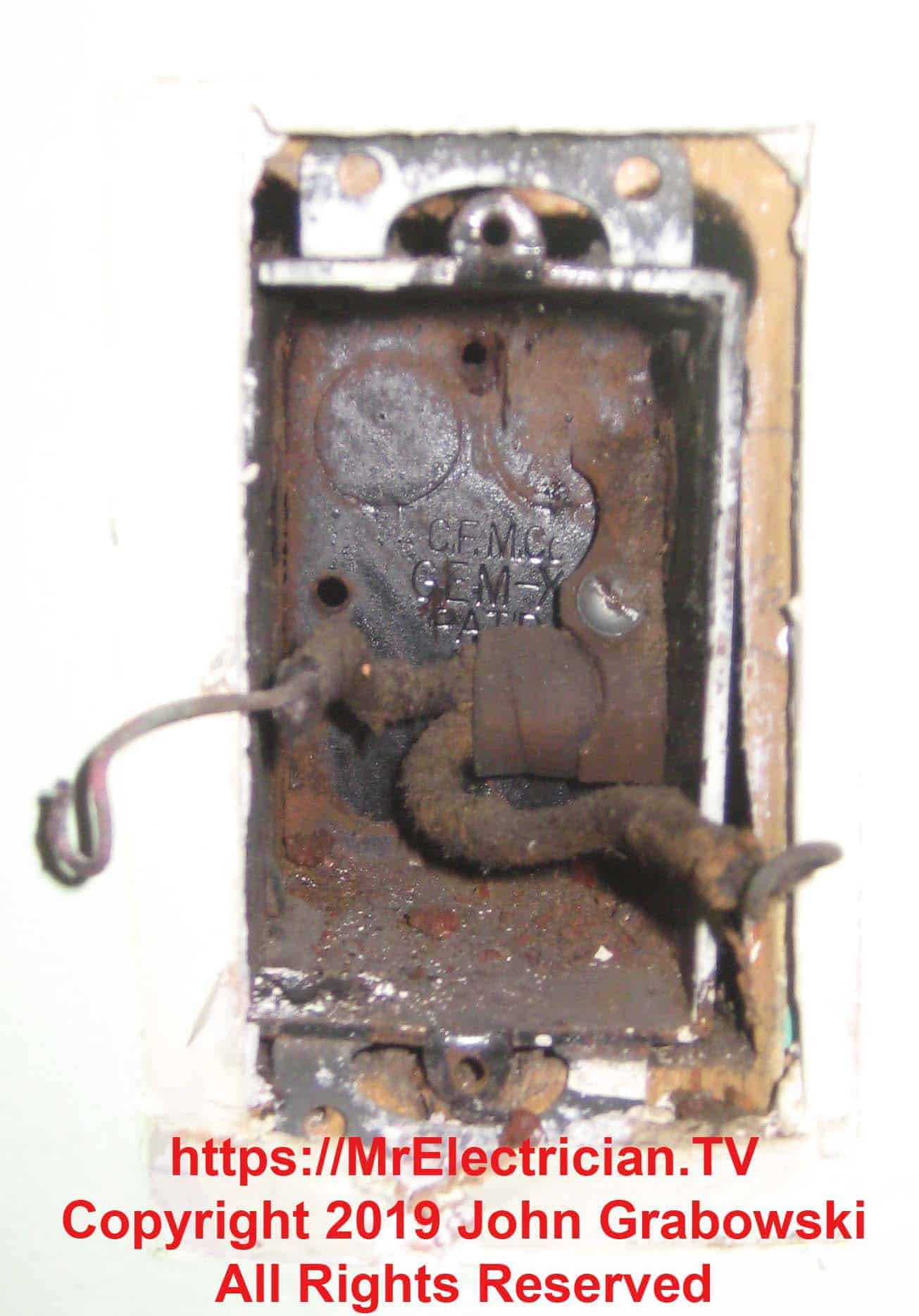
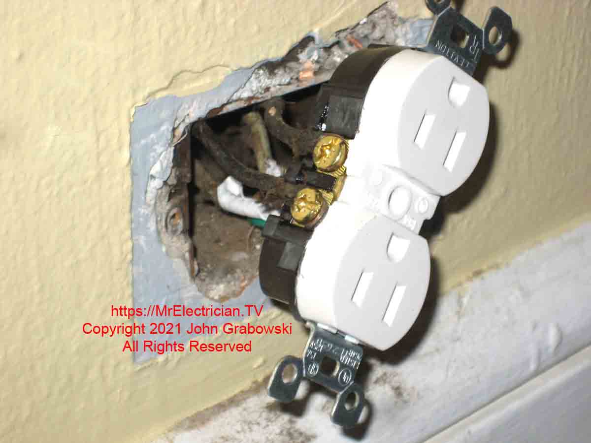
In the photo above, you can see that the existing wiring is BX cable and is clamped tightly into the box with an old-style brass bushing. This provides an adequate ground for the new tamper-resistant receptacle.
I tested each wire with my Wiggy Voltage Tester with one lead on the box and the other on the wire to determine whether it was LINE hot wire or the neutral conductor. I could tape the wires with white and black electrical tape and reuse them on a new receptacle.
Look inside the electrical box to see the type of wiring. Depending on geography and age, several choices were available that were used as part of general construction techniques. A Pre-World War 2 house could have knob and tube wiring, old-style BX metal armored cable, or even rigid metal electrical conduit with wires pulled inside.
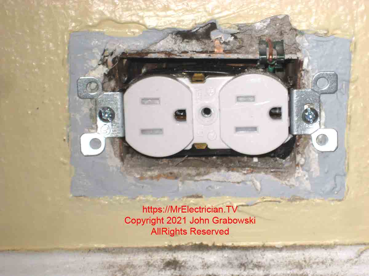
The above metal outlet box had two BX cables entering it, one from each side. There weren’t any tapped holes in the back of the box for a ground screw, so I had two options.
I could have drilled a new hole in the back of the box and tapped it for a ground screw, or I could use a grounding clip.
Homes built after World War 2 could have BX metal armored cable (AC) or non-metallic cable wiring (NM). Look closely inside the metal electrical outlet box (Which does not apply to plastic electrical boxes) to see if you have BX cable, conduit, individual conductors, or something else feeding power to the box.
If so, to ground a two-prong outlet, you can replace your two-prong outlet with a tamper-resistant self-grounding three-prong receptacle outlet. Doing this will give you a grounded three-prong electrical receptacle outlet and be code-compliant.
When working with old steel electrical boxes, I use my 6-in-1 tap tool to clean out the threaded screw holes. This helps keep the new screws from getting jammed in the screw hole.
The alternative method of grounding is to install a machine screw into the threaded hole in the back of the box and loop a green or bare wire around it to be used as a grounding conductor, also known as a grounding pigtail. The grounding pigtail then gets connected to the green screw on the receptacle. The threaded holes on old black electrical boxes were 10/24, while new boxes have 10/32 threaded holes (Number 10 screw, 32 threads per inch).
WHEN THERE IS NO GROUND AT THE ELECTRICAL RECEPTACLE
If there isn’t any effective and approved ground, you must replace the existing non-grounded electrical receptacles with a new non-grounded receptacle replacement. This is not always acceptable in a modern household.
Consequently, the National Electrical Code has allowed for the use of grounded receptacles on an ungrounded circuit. You must use GFCI tamper-resistant electrical receptacle outlets.
Read article 406.4(D)(2) in the National Electrical Code for specific details. The GFCI replacement outlets must be labeled “No Equipment Ground” on their faceplates.
Just because you added a GFCI receptacle onto a non-grounded circuit does not mean you have a grounded third prong.
You should always use a grounded circuit for sensitive appliances with microprocessors and computer equipment. If the house is so old that it does not have grounded wiring, it is long overdue for new, updated wiring. Some of my other articles may come in handy for that.
It would be best to install the GFCI receptacle at the beginning of the circuit, which would be the first receptacle on that circuit. Connect the wires going to the other ungrounded receptacles to the LOAD side of the GFCI. After that, all electrical receptacles downstream will be GFCI-protected.
All three-prong outlets installed downstream of this ungrounded GFCI outlet must be labeled “GFCI Protected, No Equipment Ground”. Labels are packaged with the GFCI outlets.
The National Electrical Code also approves installing a single conductor wire to a grounded water pipe or bonded ground rod to get the necessary ground path. You can also connect a wire to another outlet or circuit ground.
However, for the work and effort required to install a single conductor ground, you may install brand-new circuit wiring with a built-in grounding conductor. Read article 250.130(C) in the National Electrical Code for the allowances to install a grounding conductor to an ungrounded electrical receptacle.
INSTALL A REPLACEMENT FOR AN UNGROUNDED OUTLET
Most electrical receptacles in a home must be tamper-resistant to prevent children from putting things in the slots. Install the new tamper-resistant receptacle outlet (or tamper-resistant GFCI receptacle) by attaching the white neutral wires to the white or bright steel screws, which are usually on the same side as the green ground screw. Attach the black hot wires to the brass-colored screws, and then attach the bare or green grounding conductor to the green screw.
If the metal electrical box is properly grounded, you can use self-grounding, tamper-resistant receptacles, or GFCIs. For GFCI receptacles, take note of the LINE and LOAD terminals. The hot and neutral wires connect on the LINE side. The wires that go to the downstream outlets connect on the LOAD side of the GFCI.
Fold the wires back into the box as you push the receptacle back in. Screw the 6/32 screws into the box. Sometimes they can be short, and you will need to buy longer 6/32 screws.
Install a new wall plate, and the job is done. Turn the power back on and test. Note that the GFCI receptacle must be reset when it is first energized. Push the reset button, which can sometimes be difficult depending on the brand of GFCI. Sometimes I have to use a screwdriver and forcefully push the reset button.
It is a requirement that all electrical connections be tightened using a tool that limits the torque and also ensures that the correct amount of tightening is applied. For electrical receptacle outlets, you need to use a torque screwdriver.
ANOTHER EXAMPLE OF AN UNGROUNDED OUTLET REPLACEMENT
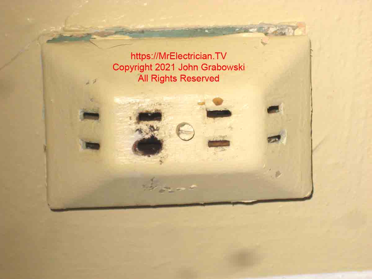
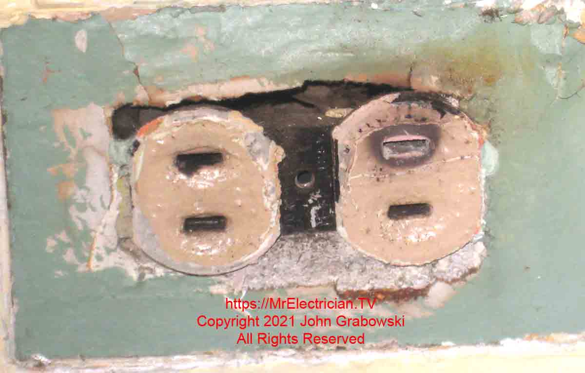
An ungrounded two-prong outlet extender with a burn mark was cause for concern. Not only was the extender burned, but also the outlet that it was plugged into. Notice the burn mark below.
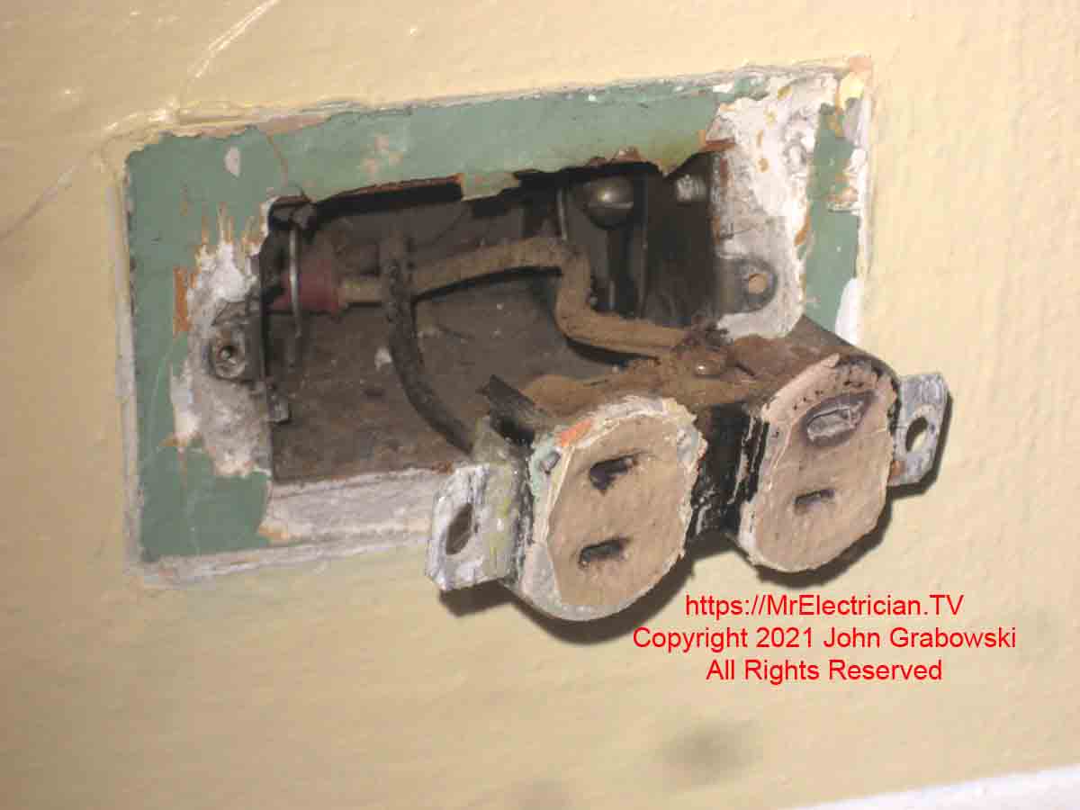
With BX cable, the grounding conductor is the metal armor of the cable. For this very reason, it is important to have all BX clamps and connectors tight.
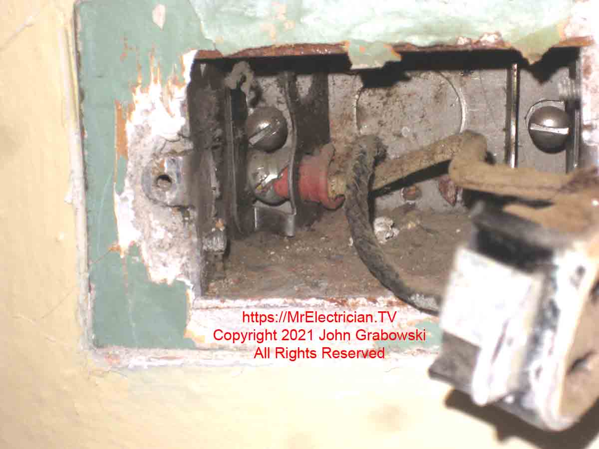
The extra cable clamp on the right side should have been removed during the original installation of this outlet. According to the National Electrical Code (NFPA 70), the clamps inside the electrical box count as one wire toward the allotted wires for that box. Read article 314.16(B)(2).
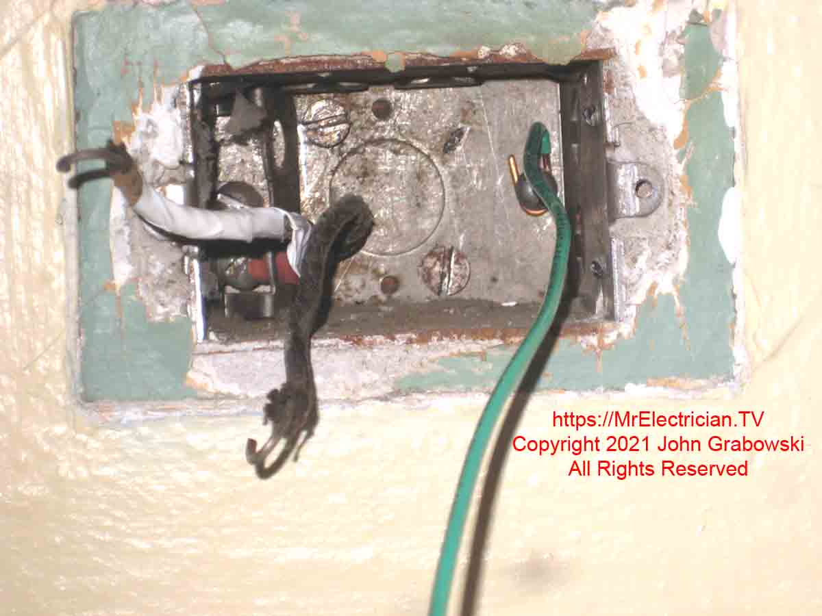
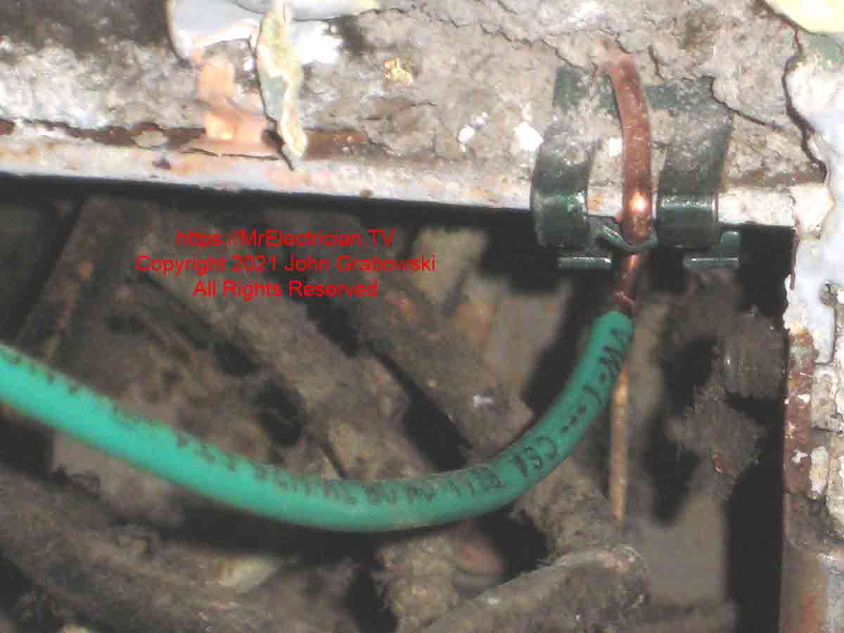
This is how to ground a two-prong outlet that will be changed to a three-prong. I used the screw from the unused clamp that was inside the electrical box to attach the grounding pigtail to the grounded metal outlet box. Unused clamps should not be left inside of an electrical box because they take up space.
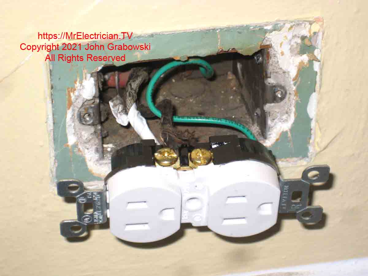
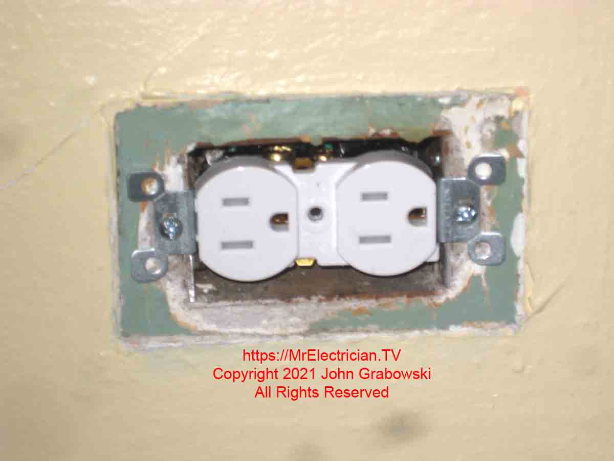
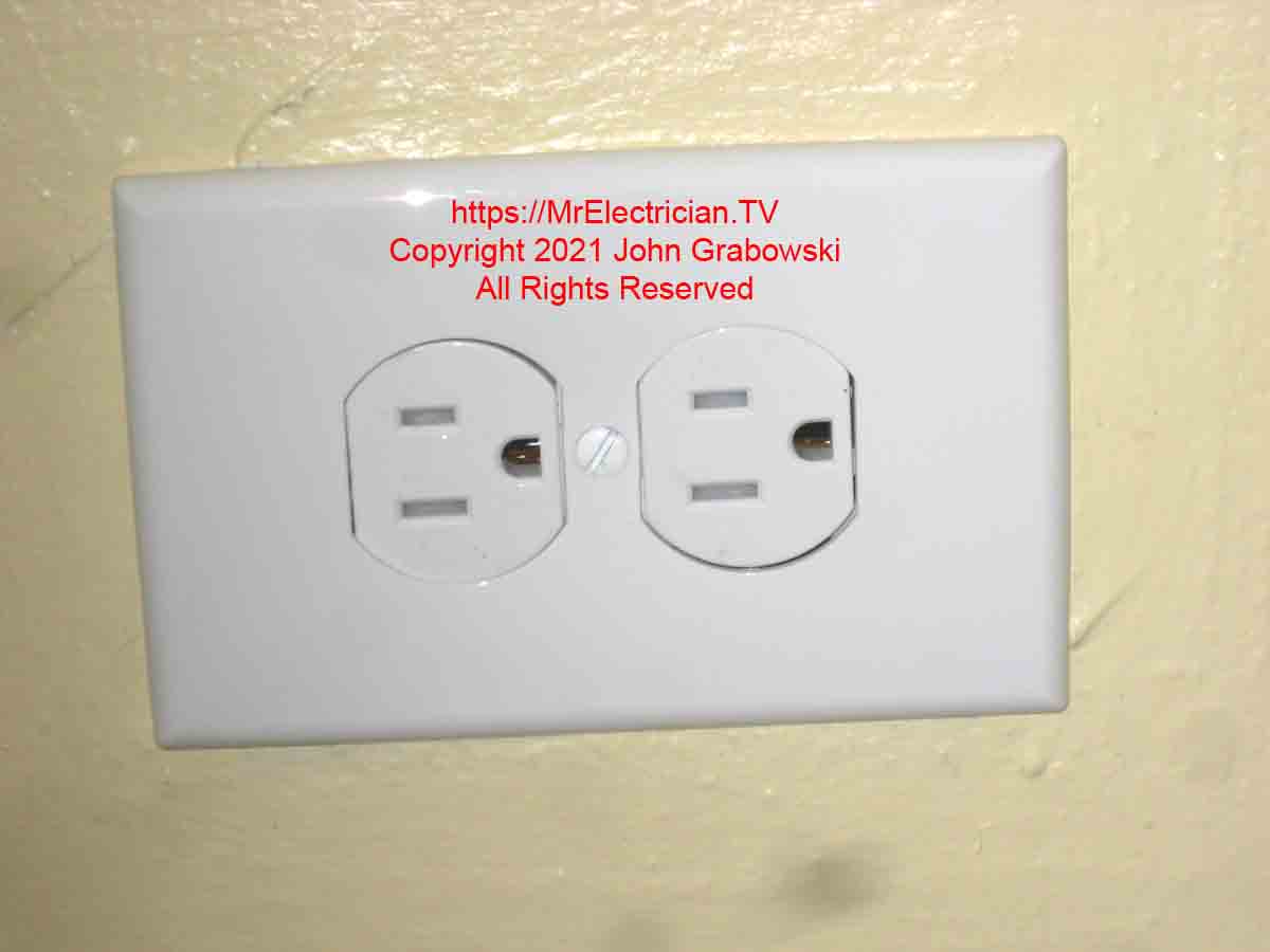
For more details to ground a two-prong outlet or about grounding electrical outlets and switches, click here to read my article with photos.
Click this link to see all of my grounding and bonding articles.
To help keep this website free, please use this Amazon link for your purchases. As an Amazon Associate, I earn from qualifying purchases.
Click here for a FREE copy of my book “Almost Everything You Need To Know To Repair a Bathroom Exhaust Fan In Your Home.”
Get your required “Emergency Disconnect, Service Disconnect” labels and stickers to satisfy the 2023 National Electrical Code requirements in article 230.85(E)(1) and (2) by going to my Redbubble Shop here.
Visit my Link Tree for free electrical information, stickers, merchandise, electrical supplies, and social media links.
