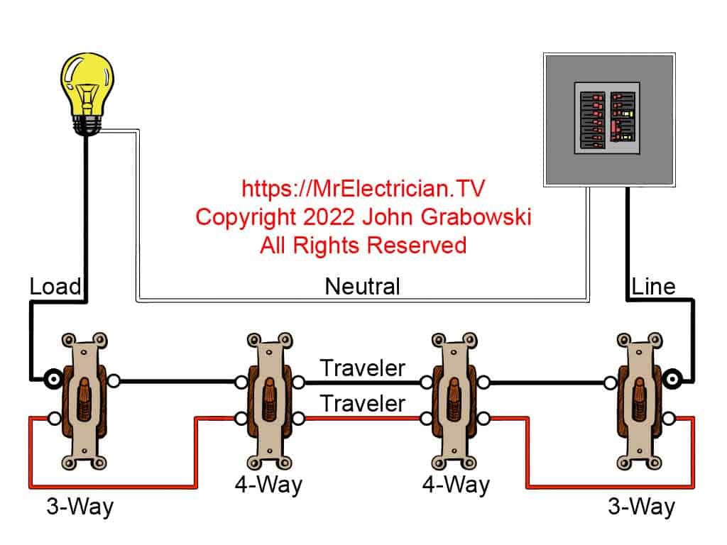
Dear Mr. Electrician: I need four-way switch diagrams to figure out how to wire four-way switches.
Answer: You can see my four-way switch diagrams above and down below. You can add as many four-way switches as you want if you have the LINE and LOAD correctly connected on the 3-way switches at each end.
NOTE: Text links below go to applicable products on Amazon. As an Amazon Associate, I earn from qualifying purchases. Using my links helps to keep this website FREE.
My four-way switch wiring diagrams are available as stickers from RedBubble. As a RedBubble affiliate, I earn a commission from each purchase.
Table of Contents:
FOUR-WAY SWITCH DIAGRAMS
The schematic diagram below shows how all four-way switches are wired. The wiring diagram further down depicts another choice of wiring method.

In some countries, the four-way is called an intermediate switch. You would continue from one 3-way switch box with the 14/3 three conductor cable (Two colored traveler wires, a white neutral, and a bare or green ground wire) in and out of each four-way switch box. The white wires get spliced through in each switch box.
The red and black wires are connected to the four-way switches. You connect the other 3-way switch at the other end with the LINE or the LOAD. See the four-way light switch wiring diagrams above and below.
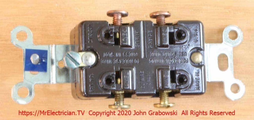
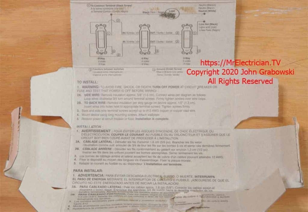
Follow the switch manufacturer’s instructions and wiring diagram, as the connections on the switch vary by manufacturer. Sometimes the switch wiring connection diagram is printed inside the four-way switch packaging box (See package example below).
Bare or green ground wires are spliced together with a grounding pigtail and then connected to the metal switch box with a 10/32 machine screw and the green screw on the switch.
Due to the proliferation of WiFi smart switches and electronic dimmers, the National Electrical Code now requires that a neutral conductor be installed in at least one of the switch boxes. See Article 404.2(C). This is accomplished by bringing the power feed into the switch box instead of the ceiling light.
Using the equipment grounding conductor as the neutral connection for a smart switch is not acceptable and can be dangerous.
At one time, some electronic switches and dimmers were approved to connect the neutral terminal on the switch to the grounding conductor. That is no longer allowed. Some smart switches for sale may not require a neutral conductor to operate, but their functions may be limited.
You must use electrical boxes approved for the number of wires and devices you install for your light switches. To determine what size boxes you should use, see article 314 in the National Electrical Code (NFPA 70).
Remember that each light switch will count as two wires when calculating your box fill. In addition, any clamps inside the box will count as one wire. Cable and conduit connectors outside the electrical box with only the locknut and bushing inside do not count as a wire.
An update in the 2020 National Electrical Code requires that all ceiling light electrical boxes where a ceiling fan could be installed must be rated for ceiling fan support. See article 314.27(C).
Below is another method for wiring four-way switches. The electrical switch box that contains the LINE and LOAD wires may need to be bigger than the other switch boxes, especially if other wires are going into the switch box.
Whenever the white wire in a cable is not used as a neutral conductor, it must be re-identified with a color other than white, gray, or green. There is no limit to how many 4-way switches can be used in a lighting switch circuit.
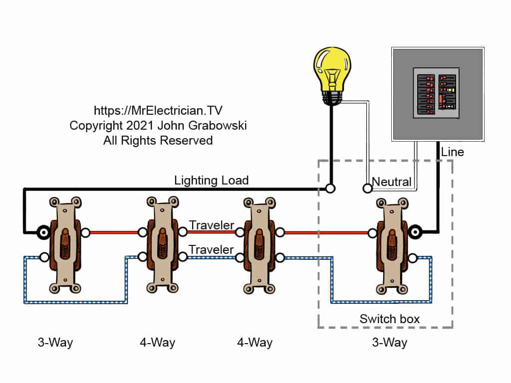
In the diagram above, splices are made, and a three-conductor cable is installed between all the switches. The white wire needs to be re-identified as a hot conductor because it is not used as a neutral in this installation.
The switch box depicted above must be extra large to accommodate all the wires and the switch.
CLICK HERE to See Stickers and Tee Shirts at Redbubble
I usually use blue electrical tape for re-identification, but any color besides white, gray, or green can be used. Some electricians will use a permanent marker-type pen to change the color.
When 3-way switches are used, the LINE and LOAD wires can only go onto one specific switch screw terminal. It is a different color screw from the other two screw terminals.
SWITCH INSTRUCTIONS
With 4-way switches, you must read the manufacturer’s instructions or wiring diagram. Sometimes, only a switch wiring diagram is printed inside the package box. The wiring connections on 4-way switches vary between manufacturers.
Bringing all the wiring into the ceiling light electrical box and wiring your 3-ways and 4-ways from there is possible. It can get crowded with many wires in the ceiling box, so you must use a larger electrical box to be code-compliant.
The National Electrical Code requires two cubic inches for each #14 wire in the electrical box. A receptacle outlet or a wall switch counts as two wires each. See Tables 314.16(A) & (B).

If all conductors are in the ceiling box, I have a wiring diagram for that installation on my 3-way switch wiring diagram page.
I did not include grounding conductors on the 4-way switch wiring diagrams to keep them simple. However, each switch and metal electrical box is required to be grounded. This is commonly achieved by splicing all the ground wires together and then adding a grounding pigtail from the metal box and each switch to them.
See my post about grounding switches and outlets properly using different wiring methods.
Click here for my post on single-pole light switch wiring diagrams.
My wiring diagrams for switched outlets might be helpful to you.
All of my wiring diagrams can be seen here.
CLICK HERE to see all of my merchandise available on RedBubble.
Visit my LinkTree for links to my social media accounts, merchandise, and electrical information.
