Dear Mr. Electrician: What are the choices of light switch wiring diagrams to wire a light switch to a ceiling light?
Answer: Light switch wiring diagrams are below. The choice of materials and wiring diagrams is usually determined by the electrician who installs the wiring and by the electrical and building codes in force at the time of construction.
NOTE: Some text links below go to applicable products on Amazon. As an Amazon Associate, I earn from qualifying purchases. Using my Links helps to keep this website FREE.
If you plan to install a ceiling fan, visit my Ceiling Fan Wiring Diagrams post by clicking here.
The architects and engineers who designed the project sometimes determine the light switch wiring methods and materials in commercial and industrial construction. Light switch wiring diagrams and wiring methods are sometimes furnished to the contractors doing the installation. For WiFi smart switches, you must adhere to the manufacturer’s wiring instructions.
Table of Contents:
- Choices of Switch Wiring Diagrams
- WiFi Smart Switches and Digital Controls
- Before Working On Existing Switch Wiring
AN UPDATE to the National Electrical Code (NFPA 70) in article 314.27(C) requires that all ceiling light electrical boxes in habitable rooms at possible ceiling fan locations be rated for ceiling fan support. This means that a fan-rated ceiling electrical box must be installed whether or not you plan to install a fan.
CHOICES OF SWITCH WIRING DIAGRAMS
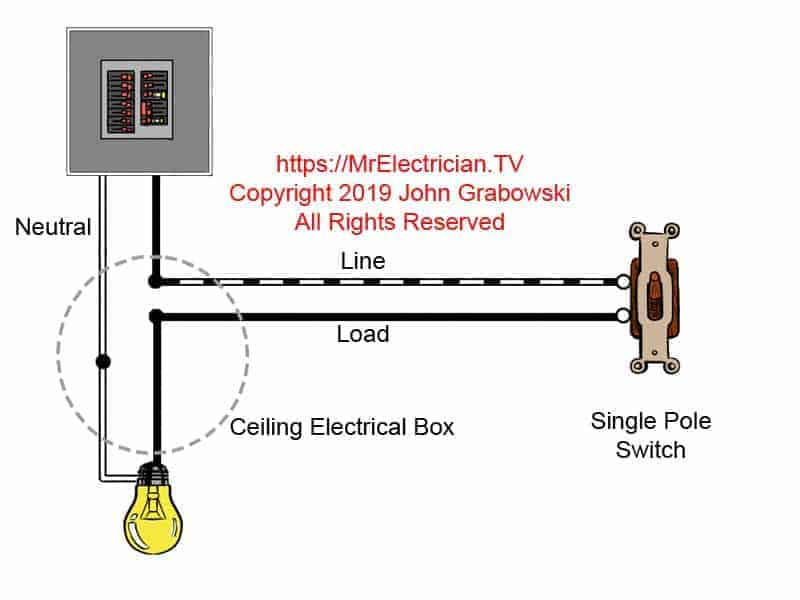
The two conductor switch wiring diagram at the top of this post is from older homes and is likely not used much anymore, depending on which code book is in force in each jurisdiction.
The two-conductor cable from the ceiling box to the light switch should have the white conductor re-identified with another color because it is not being used as a neutral but as a hot wire. However, in most cases, the white wire is not re-identified with another color.
If you see a white wire on a wall switch, it is most likely not a neutral conductor. Neutrals are rarely required to be switched.
Re-identifying a wire is done using colored electrical tape. Some electricians use a permanent marker.
Although re-identifying a wire is the code requirement, it has not been implemented as much as it should. Consequently, it is common to find a white wire in a switch box that is the hot LINE, and the black wire is the switch leg connected to the LOAD.
You cannot connect a receptacle outlet to the above type of switch wiring because there is no neutral wire in the switch box, but you can at the ceiling electrical box, assuming there is enough room for the extra wires.
It is required by the National Electrical Code (NFPA 70) that a neutral conductor be available in each light switch electrical box. See Article 404.2(C).
The neutral is needed for electronic dimmers, timers, and WiFi smart home devices that can be installed instead of an ordinary light switch. This is why the above wiring diagram is not used much anymore. All of Article 404 pertains to the installation of switches.
It is essential to follow the electrical code and other building codes for the safety and protection of your home and family.
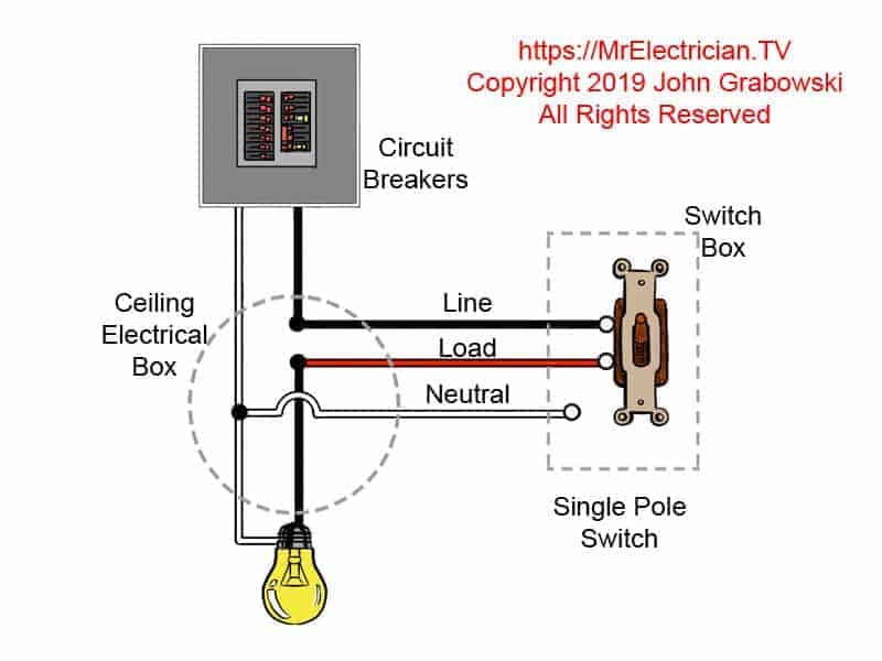
The photo above depicts the wiring diagram of a ceiling light and light switch with the power from the circuit breaker panel entering the ceiling electrical box. A three-conductor cable with a grounding conductor is used from the ceiling to send power to a light switch. The grounding conductor is not shown to simplify the wiring diagram.
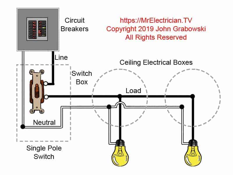
As the wiring diagram above shows, it is easy to supply power to more than one light fixture. You install a cable or conduit from a ceiling box to the next ceiling box.
The main thing to watch out for is having too many wires in one electrical box. There are code-mandated limitations as to the number of wires that can be in an electrical box, as well as physical constraints. See article 314.16 in the National Electrical Code (NFPA 70).
Generally speaking, each #14 wire requires two cubic inches of space inside an electrical box. A #12 wire needs 2.25 cubic inches. A switch counts as two wires. In addition, deductions must be made for connectors, clamps, and studs inside the electrical box. Read Article 314 in the National Electrical Code (NFPA 70).
CLICK HERE to see a Selection Of Light Switches on Amazon
If you wanted to control the two lights separately from two switches in the same box, a three-conductor cable with the ground would need to be installed to the first light instead of a two-conductor cable. At the first light, you connect the black and the white wires. The red wire would continue to the next light fixture along with a white wire using a two-conductor cable.
Of course, you could also install two separate two conductor cables to each light from the switches.

The above light switch wiring diagram depicts the power from the circuit breaker panel going to an electrical receptacle outlet, then to the next outlet, then to a single pole wall switch, and then to another outlet.
As depicted in the above light switch wiring diagram, multiple receptacle outlets can be connected with lighting outlets. Duplex receptacle outlets are made to feed the power from one receptacle to the next. The above wiring circuit was made using only a two-conductor cable with ground. The equipment grounding conductor is not shown to simplify the diagram.
If a ceiling fan is going to be mounted instead of a light fixture, a ceiling fan-rated electrical box would need to be installed. In addition, I would install a three-conductor cable with the ground from the switch to the ceiling box.
The three-conductor cable would allow the option of having two switches, one for the fan and one for the light kit on the fan. You can read my post about installing an old work ceiling fan box.
Typically, the grounding conductors would be joined together in each switch and receptacle box. A pigtail would also be connected to supply the ground connection on the green screw of each duplex receptacle and single pole switch.
If the electrical boxes are metal, they must also be grounded using an additional grounding pigtail connected using a 10/32 machine screw to a tapped hole in the back of the metal electrical box.
Sheet metal, Tek screws, and wood screws are not permitted for ground connections. See Part VII beginning with Article 250.130 in the National Electrical Code (NFPA 70).
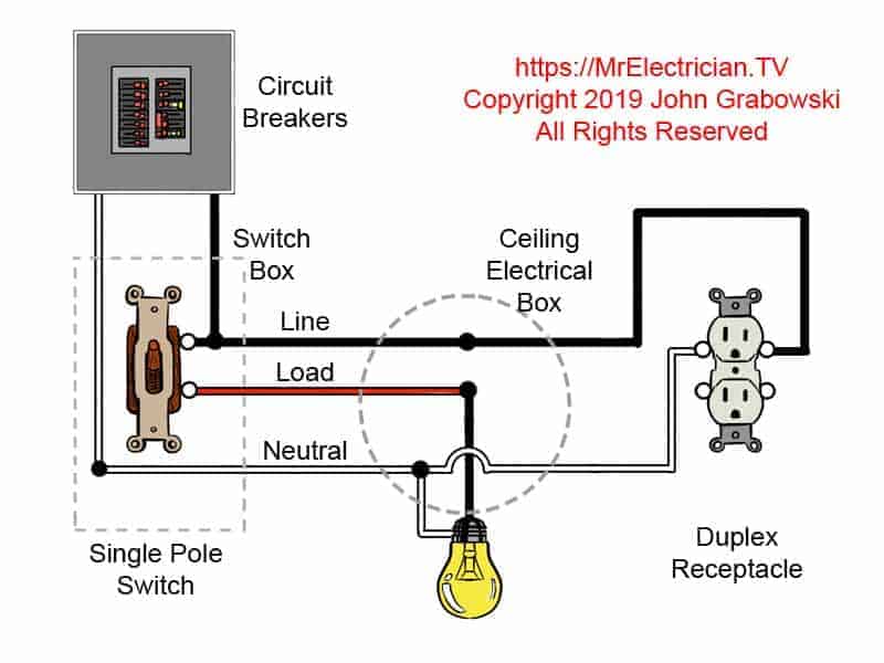
The diagram above shows a two-conductor cable from the circuit breaker panel going to a wall switch. From the switch, a three-conductor cable continues to a ceiling light. A receptacle outlet is fed power using a two-conductor cable with a ground wire from the ceiling box. The grounding conductor is not shown to keep the diagram simple.
When I rough in the wiring for the light switch to control ceiling lights, I usually install the power from the circuit breaker panel to the wall switch and only install one cable to the ceiling light electrical box or ceiling fan box.
I tend to avoid feeding other things from the ceiling box so that the box can be moved more easily if the homeowner decides to move the light location before construction is finished or many years after the construction work is done.
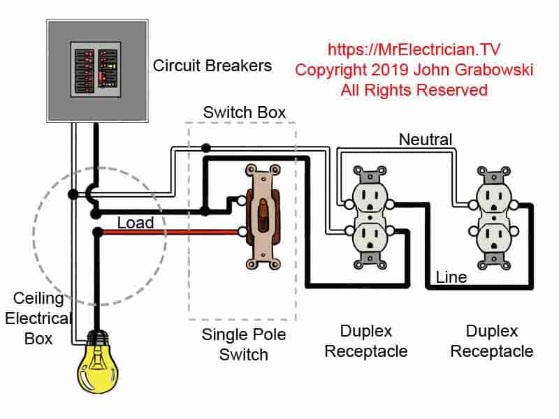
The Light switch wiring diagram above shows electrical power entering the ceiling light electrical box and then continuing to a wall switch using a three-conductor cable. A 2-conductor cable was used from the wall switch to power two electrical receptacle outlets.
As shown in the above diagram, having the neutral conductor in the switch box makes it handy to send power to other things, such as receptacles. It could also supply power to another switch that controls lights in another part of the house. A three-conductor cable must be used from the light to the switch.
Although it is permitted to wire lights and receptacles on the same circuit, I usually avoid doing that for the sake of the people living in the home. If someone plugs an electric heater or something else into a receptacle outlet and overloads the circuit, the circuit breaker will trip off. With lights and receptacles connected in this scenario, the room will have no lights until the problem is resolved.
If the lights are wired separately from the receptacles, they will remain on while the problem is fixed. If the lights and receptacles are wired with a multi-wire circuit, then it doesn’t matter as both circuits, if wired correctly on the two pole circuit breakers, will shut off anyway.
WIFI SMART SWITCHES FOR ALEXA, GOOGLE DOT, AND APPLE HOMEKIT
Electronic smart switches get wired a little differently than standard wall switches. For one thing, the LINE and LOAD connection must be made correctly. The LINE and LOAD can switch terminals with a standard single-pole wall switch. The smart switches also require a neutral conductor to operate.
You likely cannot use a smart switch if there is no neutral wire in the switch box, such as in the diagram at the top of this page. Though there may be a few types of smart switches available that are designed to operate without a neutral connection, the type of functions they offer may be limited. Do research before purchasing any smart switch or lighting dimmer.
The requirement for a neutral conductor in a switch box was only introduced into the National Electrical Code a few years ago. Before that, the electrician wired your home and would initially install the wiring in a manner suitable for them.
You cannot connect the smart switch neutral wire to the green or bare equipment grounding conductor. This can create an unsafe condition throughout the home and cause electrical appliance problems. It is forbidden by article 404.22 in the National Electrical Code.
Before purchasing a smart switch or lighting dimmer, check the manufacturer’s installation instructions and specifications.
In the United States, standard residential lighting circuits are 120 volts at 60 hertz (HZ). The switch must be compatible with that. Some of the smart switches I have seen have a voltage range from 120 volts for residences to 277 volts for commercial lighting.
To replace a wall switch with a smart switch, turn the power off using the circuit breaker for that circuit. Remove the wall plate covering the existing switch by unscrewing the two screws. Remove the switch by unscrewing the screw at the top and the screw at the bottom. Gently pull the switch away from the wall. Sometimes the wires are cut too short to pull the switch out far.
If you see a white wire on the existing switch, it most likely is not a neutral conductor. It is either a LINE or a LOAD wire. It is common to use the white wire as LINE and the black as LOAD when wiring with only a two-conductor cable. As I explained above, the white wire is supposed to be re-identified with another color but is often neglected.
BEFORE WORKING WITH EXISTING LIGHT SWITCH WIRING
Before installing the smart switch, you must identify the LINE and the LOAD wires inside the existing switch box. You cannot assume by color code which wire is the LINE and the LOAD wire. Check that the power is off using a non-contact voltage detector.
Confirm that the power is off using a category III (CAT III) or category IV (CAT IV) volt meter, or you can use a pigtail light socket with a light bulb.
Remove the two wires from the screw terminals on the side or the push-in connections in the back of the existing single-pole switch. You can use a tiny screwdriver or a paper clip to remove the pushed-in wires. Do not cut the wires. The wires in the switch box are all that you have to work with.
Pull out the white wires inside the switch box, but do not take them apart. Remove the wire connector on the white wires to expose the bare wire. Keep the joined white wires separated from the wires off of the switch.
Turn the power back on and, wearing electrically insulated gloves with glove protectors and a face shield, CAREFULLY (You can get shocked or electrocuted) check with a volt meter or pigtail light bulb to see which wire is the LINE.
Put one of your volt meter leads (Or pigtail light bulb) on the white wires and touch the other lead to one of the wires that were removed from the switch. Then check the other wire that was removed from the switch.
The switch wire that shows approximately 120 volts with the white wires is the LINE. The other wire with no voltage is the LOAD. Ignore voltage readings that are much, much lower than 120 volts. Turn the power off again.
Once you have identified the LINE, LOAD, and NEUTRAL wires inside the existing wall switch electrical box and the power is off, you can connect the smart switch following the manufacturer’s instructions.
I have noticed that some smart switch wiring diagrams from the manufacturer have the equipment grounding conductor colored yellow. This may be to indicate a bare copper wire.
Standard electrical code wiring practices in the United States require the grounding conductor to be green or a non-insulated bare wire. Other countries may have the ground wire as yellow with a green stripe or green with a yellow stripe.
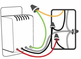
In your switch box, you should have one or more grounding conductors spliced together with a wire connector or crimp. The ground wire from the smart switch needs to be connected to that.
You will need to remove the crimp if the wires are crimped and there is no pigtail to connect to. I carefully cut the crimp parallel to the wires using my Knipex high-leverage diagonal pliers. Try not to cut the wires.
With the ground wires now separated from the crimp, twist the ends together tightly using pliers. Tightly twist the ground wire from the smart switch onto this group of ground wires. Twist an appropriately sized wire connector onto the end.
In some cases, the grounding path is established through the metal armor of the cable or metal conduit. In those instances, the metal box will be grounded, and you can connect a grounding pigtail to the back of the metal switch box using a 10/32 machine screw. Some old black enamel metal switch boxes use 10/24 machine screws. Remove all unused clamps from the inside of the box.
The smart switches are generally compatible with wall plates suitable for Decora switches though the colors may not be precisely the same.
Some of my wiring diagrams are available as stickers and imprinted on other merchandise, such as tee shirts. Click here to see everything.
For three-way switch wiring diagrams, go to my blog post.
My blog post with Four-way switch wiring diagrams is handy.
See my blog post here for switched and half-switched outlet wiring diagrams.
Click here to see my blog post about grounding switches and outlets.
To see all of the categories of electrical topics discussed by Mr. Electrician, click here.
For an interesting article on the operation of various types of switches, click here.
Visit my Link Tree for links to my YouTube channel and other social media sites with more free electrical information and photos.
All my switch and switch box installation articles can be seen by clicking here.
