Dear Mr. Electrician: Where can I find ceiling fan wiring diagrams showing the blue and black wire connections?
Answer: Below are my ceiling fan wiring diagrams with two-switch diagrams further down. In addition, I have provided links to some ceiling fan manufacturers for replacement parts and internal ceiling fan wiring diagrams.
NOTE: Some links below go to applicable products on Amazon. As an Amazon Associate, I earn from qualifying purchases. Using my links helps to keep this website FREE.
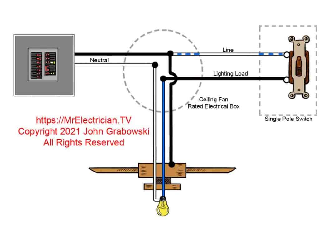
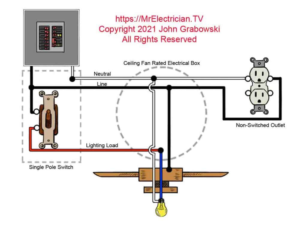
The ceiling fan wiring diagram at the top of this page depicts a standard wiring method used during the construction of houses long ago.
In this ceiling fan wiring diagram, the blue wire on the ceiling fan is connected to the LOAD side of the wall switch to control the fan’s light. The black fan wire is connected to the LINE enabling the pull chain switch on the fan to control the fan motor independently of the wall switch.
It is not unusual to see a white wire used as the hot or LINE wire on a switch. However, the white wire must be re-identified with another color other than white, gray, or green. I use rolls of different colors of electrical tape for re-identification. Some electricians will use a permanent ink marker-type pen to change the color of a wire.
With the construction of a new home, the National Electrical Code requires that a neutral conductor be installed at most wall switch electrical box locations. The neutral lets you use an electronic device instead of a standard wall switch to control your ceiling fan and light. Read article 404.2(C), where the neutral is called the “Grounded Circuit Conductor.”
Table of Contents:
- One Switch Fan Wiring Diagrams
- Two Switch Fan Wiring Diagrams
- Ceiling Fan Remote Controls
- Which Way Should The Fan Blow?
- Electrical Boxes Rated For Ceiling Fans
- Information To Help With Ceiling Fan Repair
- Links to Articles Depicting Ceiling Fan Installations
I have never seen wiring diagrams for a ceiling fan attached or printed on the fan housing or motor. Most ceiling fan internal wiring diagrams depicting the blue wire and the black wire are included with the installation instructions.
I recommend you read the manufacturer’s installation instructions for your ceiling fan before you buy the fan. They are usually available on the manufacturer’s website. Some ceiling fan manufacturer links are at the bottom of this post.
The following ceiling fan wiring diagrams for wall switches can be used for new construction and old work remodeling and renovation.
CEILING FAN DIAGRAMS
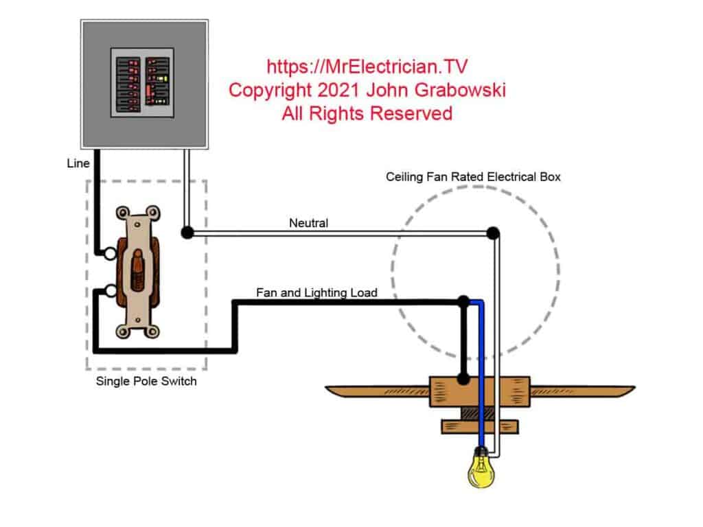
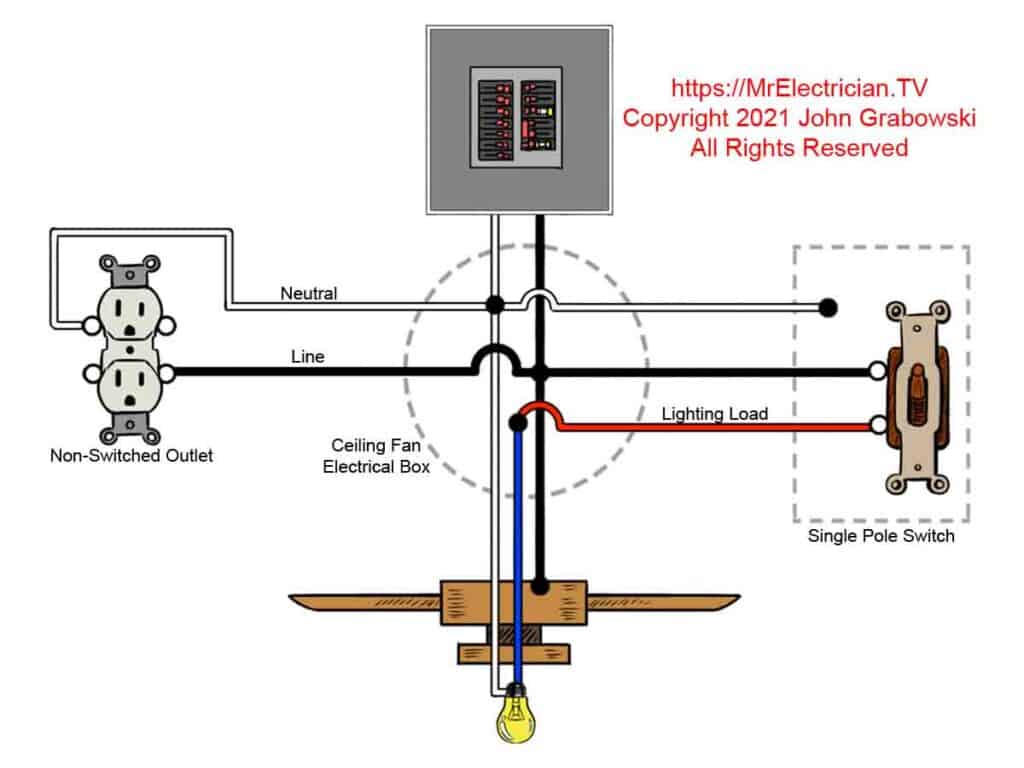
The above ceiling fan wiring diagram depicts the power going into the switches’ electrical box first. Then a switched hot and a neutral go up to the ceiling mounted electrical box on a two conductor cable. This method connects the black wire for the fan motor and the blue wire for the ceiling fan light to the LOAD wire from the wall switch.
The same wall switch controls the fan and light. However, the wall switch can be left on, and the fan and light can be controlled separately using the pull chain switches.
A remote control unit can be added to this ceiling fan. The wall switch would need to be kept in the on position.
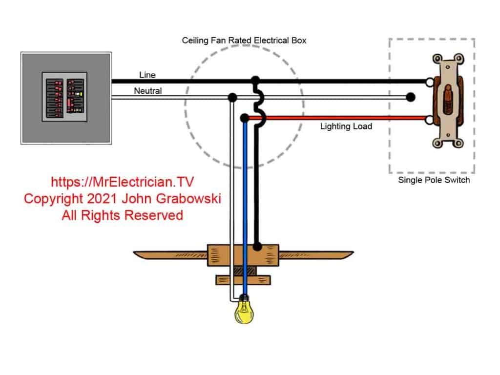
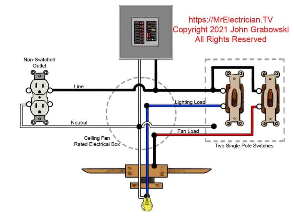
Above is shown the method that would be used so that a neutral conductor is available at the switch box from the power source in the ceiling fan-rated box. The blue fan wire is connected to the red LOAD wire from the wall switch. The black fan wire is connected to the LINE. The wall switch controls the light on the ceiling fan, and the pull chain switch controls the fan motor independently of the wall switch.
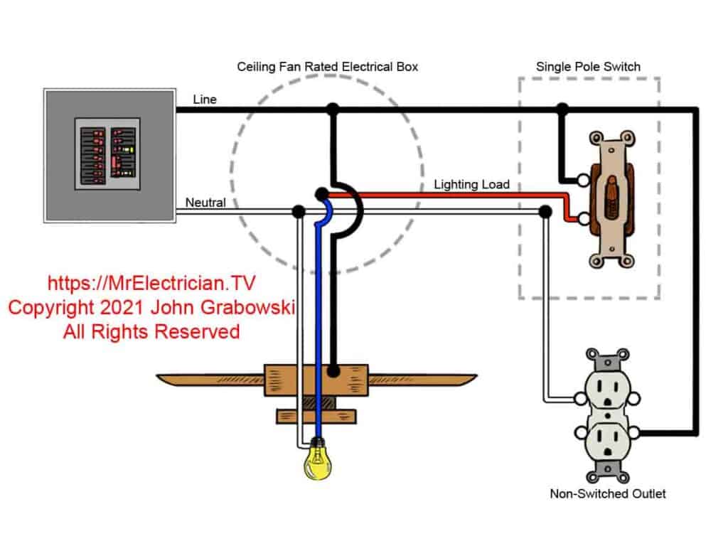
By having the hot and neutral in the switch box, it is possible to tap into the power there for other things such as an electrical outlet. The diagram above depicts the red LOAD wire from the wall switch connected to the ceiling fan’s blue wire to control the light. The fan motor is controlled independently of the wall switch using the pull chain switch on the fan because the black fan wire is connected directly to the LINE.
The electrical outlet is always on and not controlled by the wall switch.
A three-conductor cable is necessary to bring the LINE, Neutral, and LOAD conductors to the ceiling box. The wiring diagram above depicts the connections for the blue wire for the light and the black wire for the fan motor. The wall switch controls the light, and the fan motor is controlled by the built-in pull chain switch independently of the wall switch.
The electrical outlets depicted above and below are both on at all times and are not controlled by the wall switch.
A 2 1/8″ deep ceiling fan box must be used for the above ceiling fan installation. There are too many wires for a standard 1 1/2″ deep electrical box. The wall switch’s red LOAD wire connected to the blue wire on the fan means that the wall switch only operates the light on the fan. The built-in pull chain switch operates the fan motor with the black fan wire connected to LINE.
FAN DIAGRAMS FOR TWO SWITCHES
If using the diagram above, you will need a deep ceiling fan-rated box to handle all of the wires. The National Electrical Code requires two cubic inches inside the electrical box for each #14 conductor. Read article 314 in the National Electrical Code (NFPA 70).
The wiring diagram above depicts the blue wire from the fan connected to the LOAD wire from one switch. The black wire on the fan is connected to the other switch LOAD wire. The light and fan are controlled independently using the wall switches. There is no need to use the pull chains unless you want to change the fan speed.
Reversing the direction of the fan motor is accomplished by moving the switch on the top of the fan motor up or down or sideways.
Alternatively, a dimmer can be installed for the light, and a fan speed control can be installed to control the fan’s speed from the wall.
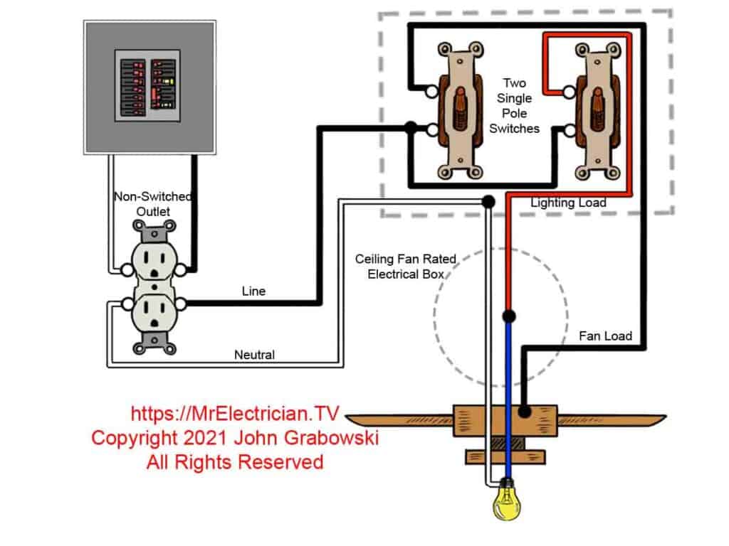
The switch boxes will need to be deep enough to accommodate all wires. Each switch counts as two wires.
FAN REMOTE CONTROLS
A remote control receiver can be wired onto most ceiling fans. Read the remote control manufacturer’s instructions before purchasing the remote control. Although remote controls for ceiling fans are very convenient, they were also the reason for most of the service calls I received from clients about fans that stopped working. Either the fan remote control or transmitter went bad, or the radio connection between the transmitter and receiver was broken.
The transmitter/receiver broken connection is usually easy to correct, but every manufacturer seems to have a different method. Sometimes you need to shut the power off to the circuit, then turn it back on and hold a button on the transmitter for several seconds to restore the connection. Best to check with the remote control manufacturer.
I like having the remote control at the switch location, such as with the Lutron Caseta wireless ceiling fan control. Changing a bad wall switch is easier than replacing the receiver mounted inside the ceiling fan canopy.
If you don’t want a remote control but would prefer to have all fan control options at the wall switch location, you should search for a ceiling fan with a wall control that will operate over the existing wiring. Sometimes, it is just a remote control that fits in the wall like a regular wall switch.
Casablanca Fan Company Intellitouch models have this feature.
WHICH WAY SHOULD THE CEILING FAN BLOW?
I have often been asked in which direction the ceiling fan should blow. Having read the instructions for many ceiling fans, I noticed it varies by manufacturer. Some say the fan should blow down in the winter and then up in the summer. Others have said the opposite.
My answer is based on the individual. If you want to feel a breeze, have the fan blow down. If you do not want to feel a breeze, have the ceiling fan blow the air upwards.
There is a switch on most fans manufactured without remote controls that changes the fan’s direction. The switch is on the motor, either on top or side. The reversing switch will move up and down or side to side depending on the fan. You will need a ladder to access this switch.
Whichever way the fan blows, it will mix the air so that all the hot air is not on the ceiling and all the cool air is not on the floor.
CEILING FAN ELECTRICAL BOX
If you are planning to wire a house or an addition, any electrical box you install in the ceiling for lighting must be rated for ceiling fan support if it is in a location where a ceiling fan could be installed, whether you plan to or not. Read article 314.27(C) in the National Electrical Code for the exact requirements for your installation.
The majority of existing homes were not constructed with accommodations for ceiling fans. The electrical box must be changed to a fan-rated one to install a ceiling fan where a light fixture is currently mounted.
Plastic and metal fan boxes are available for retrofitting into an existing ceiling opening, each with a different weight rating. Some get installed between ceiling joists, while others are made to be attached to the side of a joist. There are others, such as a pancake fan box that mounts directly to the bottom side of a joist.
Fortunately, several fan-rated electrical box types can replace an existing electrical box without damaging the ceiling. However, the replacement gets tricky in very old houses with small black pancake-type electrical boxes with very old wires. See my article and photos depicting the replacement of this type of box.
FAN WIRING REPAIR
As with many items in your home, ceiling fan replacement parts are available to repair your ceiling fan. It is essential to know the manufacturer’s name, the model number, and the name of the ceiling fan. Sometimes the serial number is needed as well.
Most ceiling fans have a nameplate on top of the motor. Consequently, a stepladder would be needed to see it.
CLICK HERE to See Ceiling Fan Repair Parts and Accessories at Amazon
A flush mount fan must have its cowling dropped to see the fan motor nameplate. The cowling is held in place by a few screws around the perimeter. However, the fan blades may prevent the cowling from coming down enough so that you can see the fan motor top. With the cowling down, you can see the ceiling fan wiring connecting to the house’s electrical circuit.

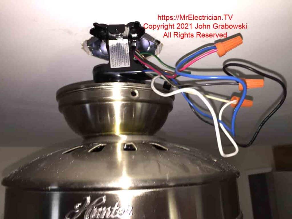
Remove the fan blades with a large flathead screwdriver to get the cowling down. Remove the blades where the bracket attaches to the motor. Do not remove the blade from the metal bracket. Sometimes only a Philips screwdriver will work.
Some ceiling fan blades are held in place with spring clips. Removal of the ceiling fan blade is just a matter of releasing the clip and pulling or pushing the fan blade.
I found that the greatest challenge with ceiling fan repair is the replacement of the pull chain type speed control switch built into the ceiling fan. The switch is easy to remove and replace with a new one, but the wiring connections are tricky.
Always label the wires before removing them from the old pull chain speed switch. You may need a magnifying glass to read the terminal names or numbers on the old switch.
USEFUL CEILING FAN LINKS
If you currently have a switch-controlled wall outlet and would like to install a ceiling fan using that switch, click here to see my article for details.
This article depicts changed outlet wiring for a ceiling fan using metal switch boxes.
This article depicts the installation of two switches for a fan and light using existing wiring.
To wire your ceiling fan to control it from more than one wall switch location, read my article with 3-way switch wiring diagrams.
My article with light switch wiring diagrams may also be helpful to you.
All of my articles, with photos, about ceiling fans can be found by clicking here.
My article that depicts electric motor wiring diagrams may be helpful if you are repairing a fan motor. Ceiling fans commonly have shaded pole motors.
Click here for Hunter and Casablanca Ceiling Fan replacement parts, wiring diagrams, and manuals.
Click for Harbor Breeze Ceiling Fan parts and accessories.
Emerson Ceiling Fan replacement parts are available here.
Some parts and Accessories for Hampton Bay Ceiling Fans are here.
Progress Lighting Ceiling Fan manuals with wiring diagrams.
Click here for the different grounding methods available for grounding switches and outlets.
To help keep this website free, please use this Amazon link for your purchases. As an Amazon Associate, I earn from qualifying purchases.
Click here for a FREE copy of my book “Almost Everything You Need To Know To Repair a Bathroom Exhaust Fan In Your Home.”
Get your required “Emergency Disconnect, Service Disconnect” labels and stickers to satisfy the 2023 National Electrical Code requirements in article 230.85(E)(1) by going to my Redbubble Shop here.
Visit my Link Tree for more free electrical information and some unique products.
