Dear Mr. Electrician, How do I add a bathroom fan switch to my existing bathroom light switch so that I can control my bathroom fan separately?
NOTE: Some text links below go to applicable products on Amazon. As an Amazon Associate, I earn from qualifying purchases. Using my links helps to keep this website FREE.
Answer: Depending on how the home was wired initially, adding a bathroom fan switch could be changing some connections at the existing light switch. Then, you could install a combination device with two single-pole switches on one strap.
Table of Contents:
ADDING BATHROOM FAN SWITCH
I have had this request a few times, and in some cases, all I needed to do was open up the existing wall switch and make some changes. I would remove the wall plate, unscrew the screws holding the switch in the switch box, and pull the switch away from the wall to access the wires. Sometimes, the most challenging part is getting the paint off the wall plate screws.
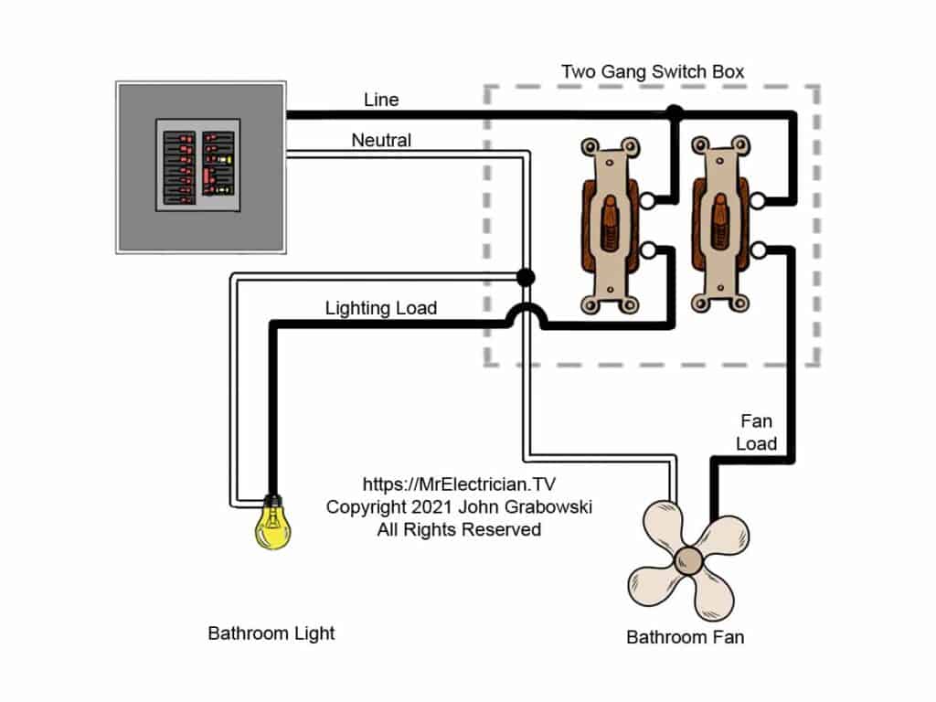
Adding a bathroom fan switch is possible when there is a cable inside the electrical switch box that goes to the bathroom light fixture and another cable that goes to the bathroom fan. A second switch could be added without installing additional wiring. See the bathroom fan wiring diagram below.
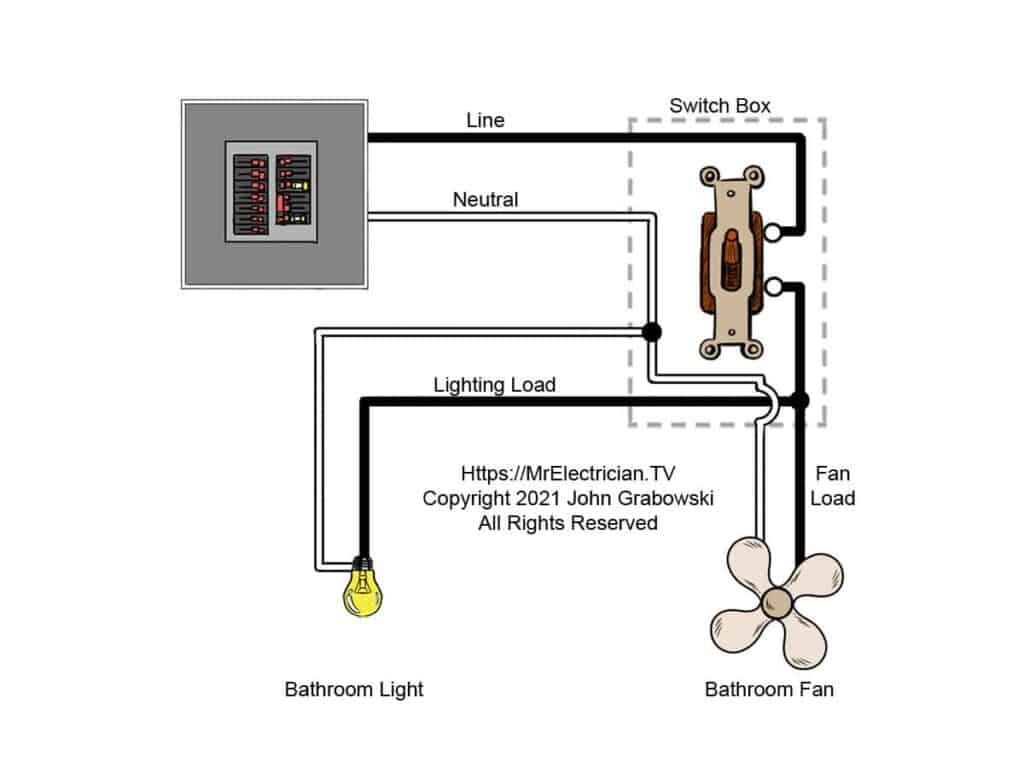
The original wiring would consist of a cable bringing the power to the switch box and two cables going to the fan and the light separately. Other cables could supply power to different parts of the home. They would just be connected to the hot and neutral.
All white neutral wires would be spliced together using a wire nut or another wire connector. The black wires to the fan and the light would be spliced together with a black pigtail, which would be connected to the single wall switch.
The black wire from the power cable is connected to the other terminal on the switch. When the switch is turned on, power flows simultaneously to the fan and light.
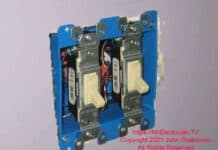
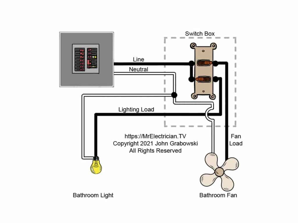
Inside the wall switch electrical box, I would separate the black wire that goes to the bathroom fan from the black wire that goes to the light fixture. Then, a combination switch device such as the one below would be installed to replace the old single-pole switch.
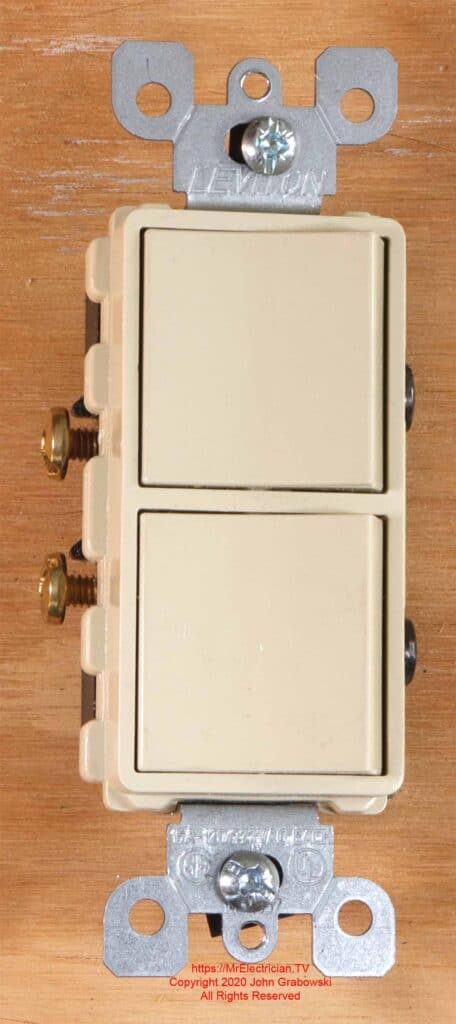
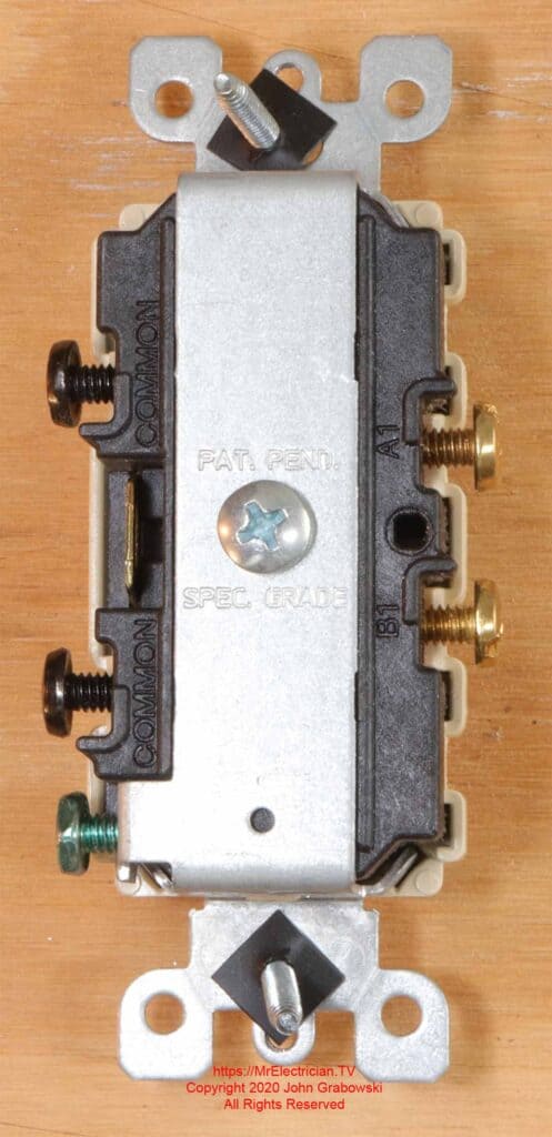
In the replacement scenario above, the existing hot wire in the switch box would connect to one of the black screw terminals. Then the black wire for the fan goes under one of the brass screws. The other black wire for the lighting goes under the other brass screw. The grounding conductor only goes under the green screw.
In the photo below, you can see the wiring terminals. Both screws on the left side are the hot connection which is evident because of the break-off tab between them. Two separate circuits can feed this device by breaking off that little tab.
ADDING WIRING FOR A NEW SWITCH
Because of the original installer’s wiring method, a quick wiring connection change is not always possible. In that case, the next choice would be to install a new separate cable up to the fan or to the light fixture to make it possible to have two separate switches.
Below is a job where I replaced the entire bath fan unit and also installed a separate wall switch for the fan. The old bathroom exhaust fan was wired from the ceiling light fixture next to it, so a new cable was needed from the switch location to the new bathroom fan.
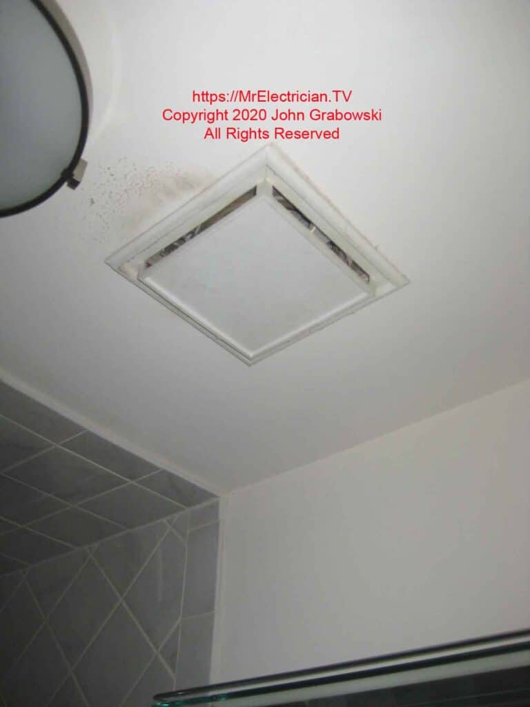
The replacement of the fan unit was considered a repair and did not require inspection by the city electrical inspector. The new wiring and switch box did have to be inspected, but because it was a small job, no rough-in inspection was needed. I applied for the electrical permit a few weeks before starting the work.
The existing switch electrical box was full to capacity with wires, so a two-gang old work switch box was necessary to be code-compliant. Article 314.16 in the National Electrical Code explains how to calculate the cubic inch capacity required for each wire size.
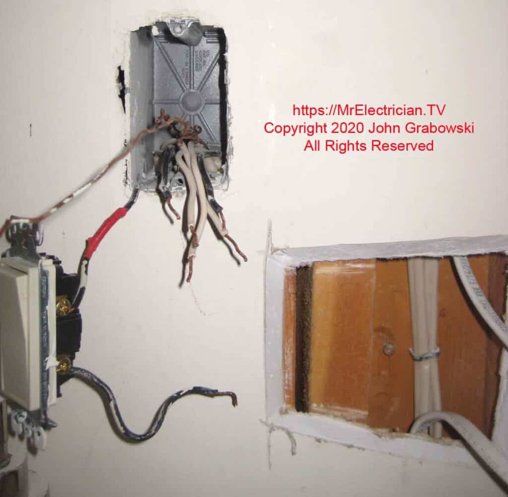
I developed my own method of cutting access holes in walls where I needed to install wiring. I cut the hole holding my compass saw at an approximately 45-degree angle with the blade tilted inward, which makes it much easier to patch. See the photos at the end for the patch jobs.
The existing switch box had six wires plus grounds. One black-and-white wire pair was the electrical feed supplying power to the box, and another black-and-white pair supplied power from this switch box to the switch box for the hall light.
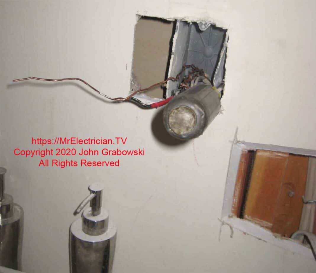
The last pair of wires went to the existing bathroom ceiling light. I labeled the black wire and the LOAD that went to the light fixture with red electrical tape.
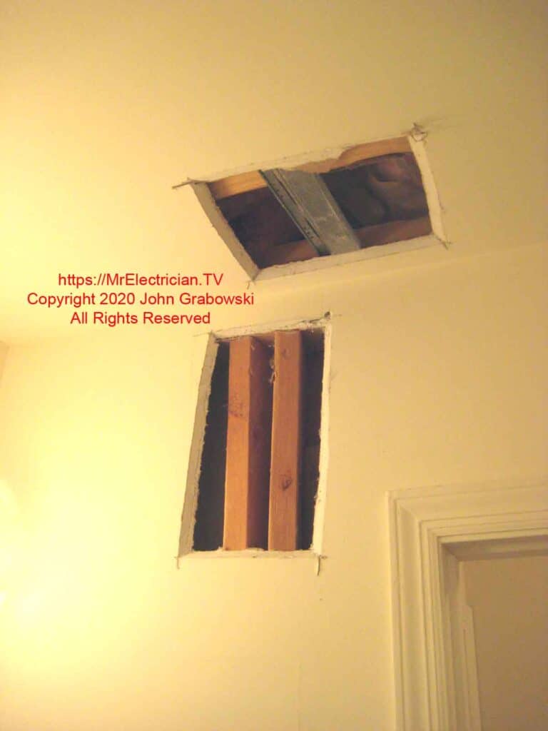
I needed to cut access holes in the ceiling and the wall to get the new cable down to the existing switch location. The ceiling had trusses for joists, which made it easy to fish the new cable across.
The wall was more difficult because of the medicine cabinet, the closet behind this wall, and the proximity to the door. The holes above were cut with the saw angled at 45 degrees.
I used to cut these holes with my keyhole, or compass saw. However, since I purchased my oscillating multi-tool, I have used it to cut access holes in drywall.
After I cut the access holes in the drywall, I had to drill some holes using my half-inch Milwaukee Angle Drill. I had to drill through the wall’s top plate to get into the ceiling. I also had to drill through some wall studs to get the new cable to the existing switch location.
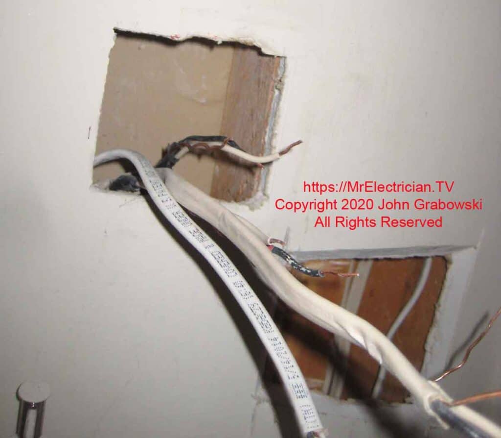
Above is the new Romex cable I installed next to the existing wiring, which will be used again when the new switches are installed.
Before I removed the old switch box, I held the new old work plastic switch box on the wall and traced a line to cut out the opening. It is easier to remove the old box with the bigger hole.
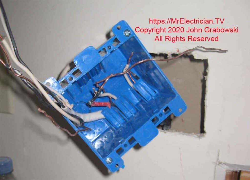
I pull the wires into the new two-gang old-work switch box a little at a time. As I push the box closer to the wall, I continue to pull each wire until the box sits inside the wall.
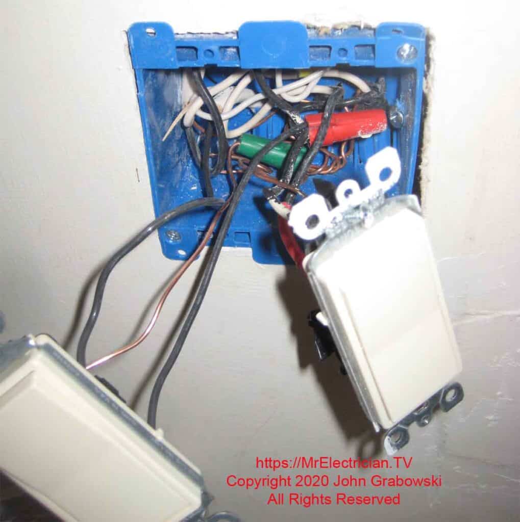
Notice the sheet metal screw driven through the old-work box into the wood stud on the right side. This gives the box more stability.
PATCHING THE HOLES
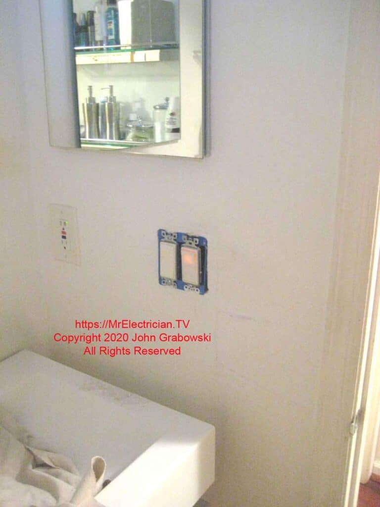
The almost finished switch installation. When I added the bathroom fan switch, the homeowner wanted her existing locator light switch installed.
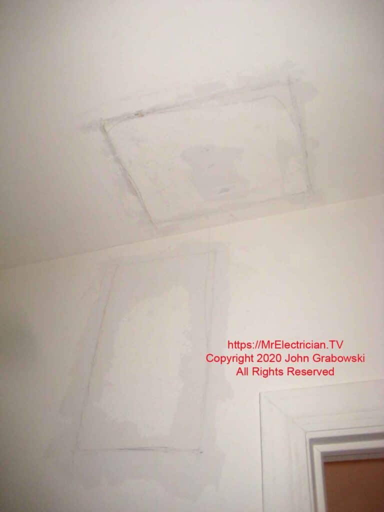
The holes above were patched using the old pieces of drywall that had been cut out. The drywall edges on the wall and the cut pieces were each buttered with a thick coat of joint compound. Some of the compound will ooze out after the piece is pushed into place. Use a wide-blade putty knife and smooth it down.
Due to the drywall’s angle cut, the joints do not need to be taped. Let the joint compound dry overnight. The next day, smooth it a little with a damp sponge or fine sandpaper and then apply a second coat. A third coat may be needed to finish.
For large ceiling pieces, I will install a block of wood or two to screw the piece of drywall into to keep it in place until the compound dries.
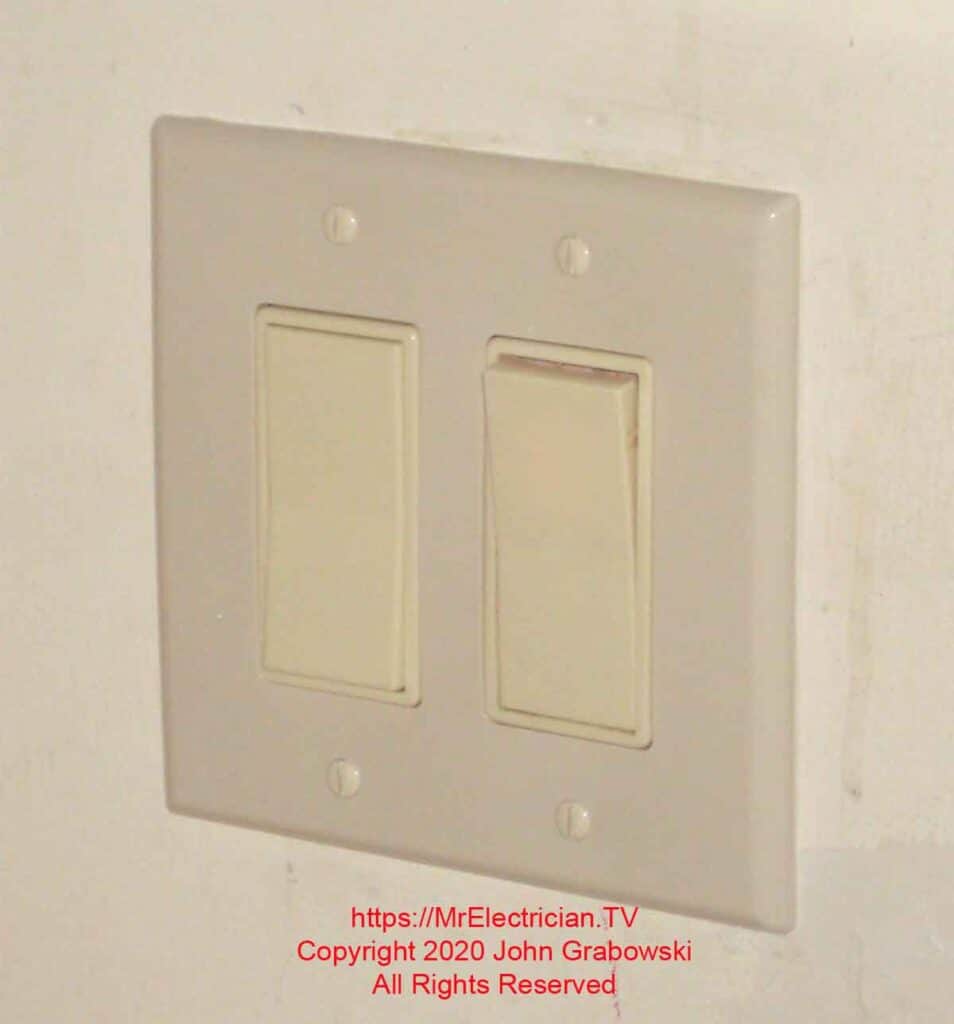
Adding a bathroom fan switch finished product above.
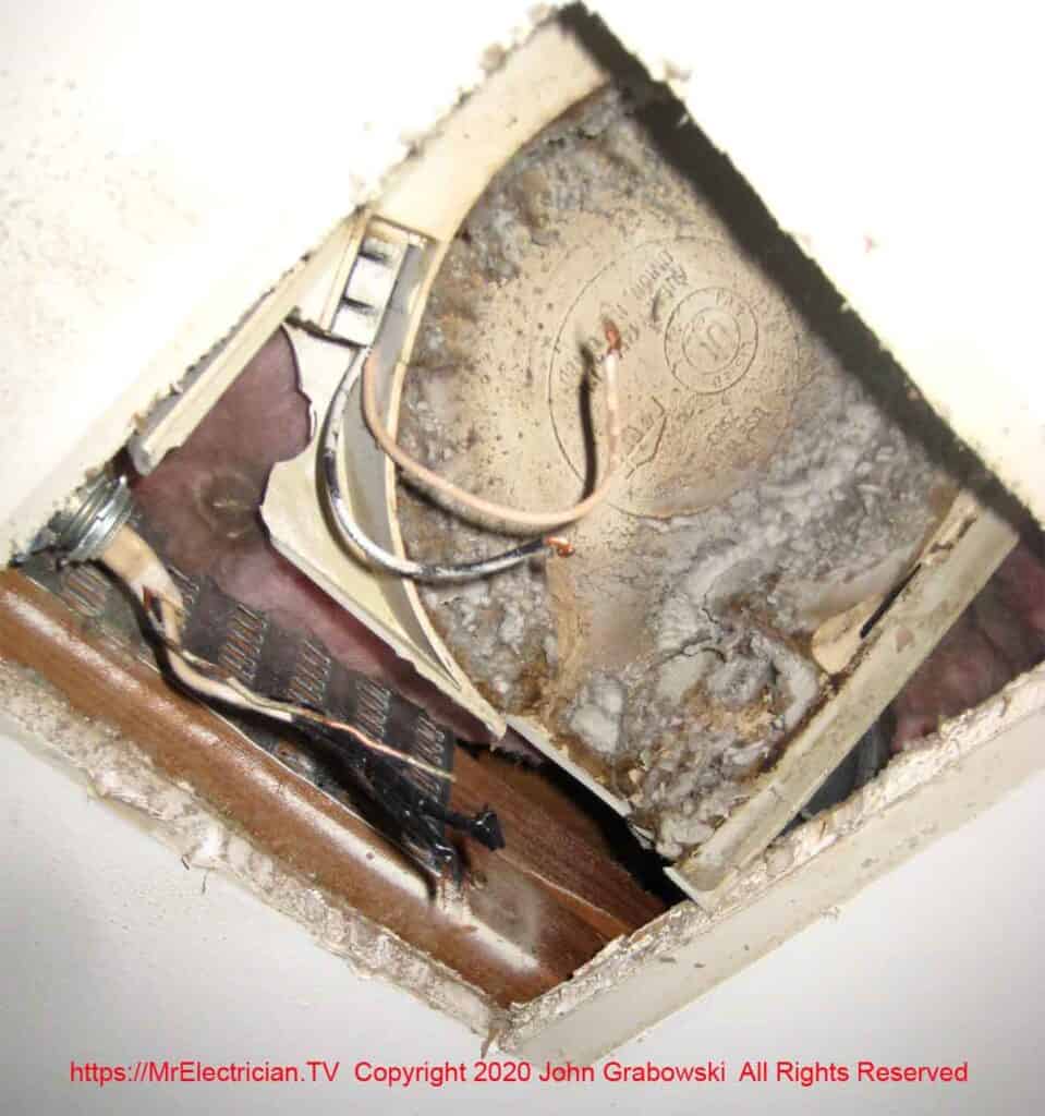
The old ceiling fan had a plastic housing, which made removal easier. I just kept breaking pieces off with my pliers.
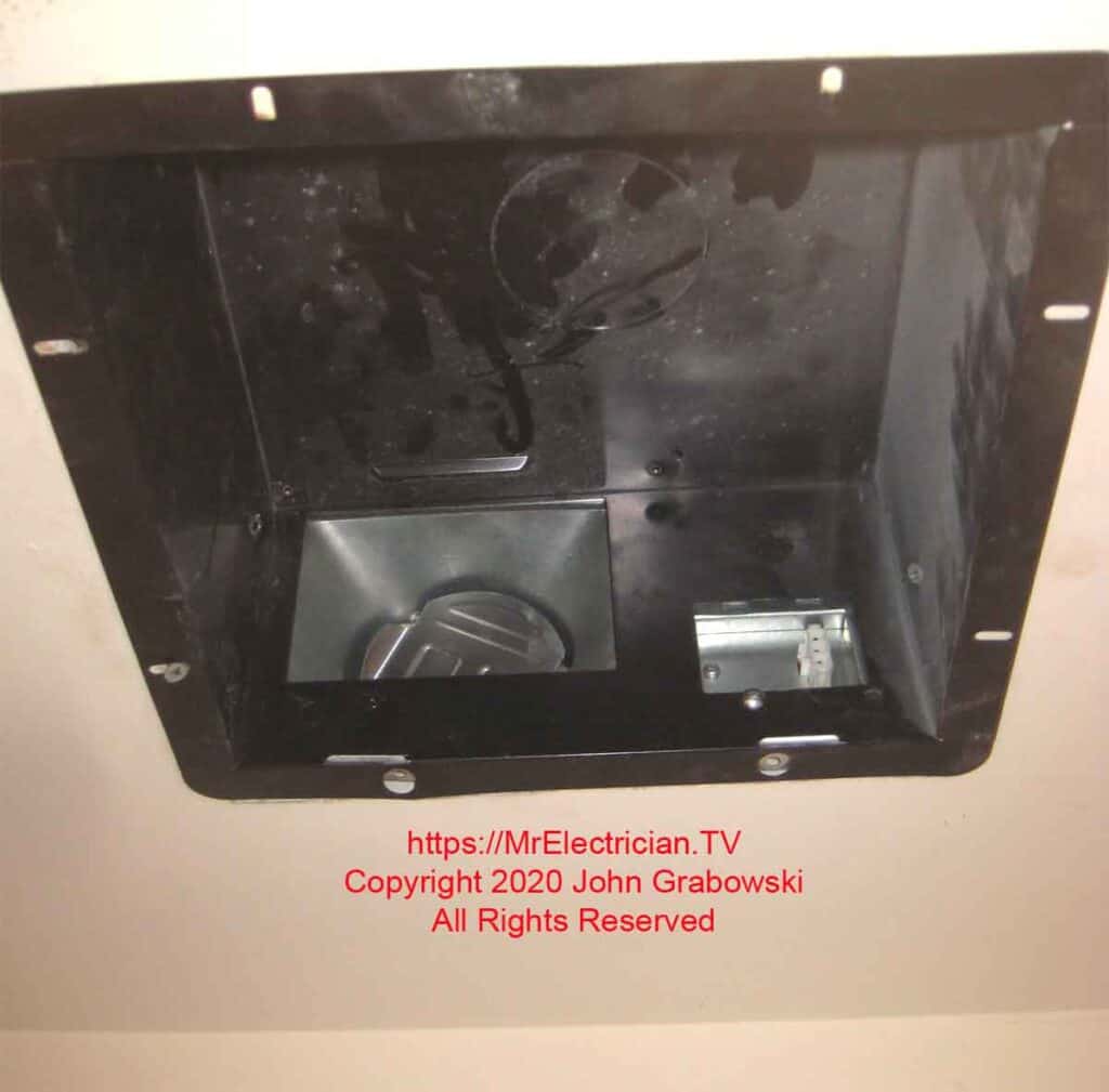
The new Panasonic bathroom fan housing has a dusty interior, which is different from my work. I usually wipe them down before installing the motor and grill. Panasonic fans are made to retrofit into existing fan locations.
I particularly like the WhisperFit Panasonic fan models as they have a low profile and are rated for use with either 3-inch or 4-inch air ducts.

Above is the finished Panasonic bathroom fan grill, controlled by a separate wall switch.

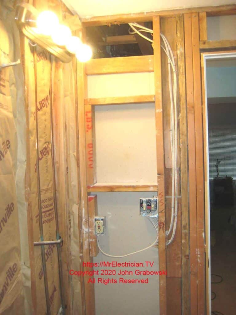
Below is a photo from a different bathroom remodeling job where the drywall was removed from the walls. You can see the wiring route the original electrician had to take to avoid the medicine cabinet.
When I started this job, I moved that GFCI electrical outlet up to the same height as the switches before adding a bathroom fan switch.
Below is my short video from YouTube about adding a bathroom fan switch.
My post with light switch wiring diagrams may be helpful to you when adding a bathroom fan switch.
Click to see my blog post about properly grounding outlets and switches.
To help keep this website FREE, please use this Amazon link for your purchases. As an Amazon Associate, I earn from qualifying purchases.
Click for a FREE copy of my book “Almost Everything You Need To Know To Repair a Bathroom Exhaust Fan In Your Home.”
Get your required “Emergency Disconnect, Service Disconnect” labels and stickers to satisfy the 2023 National Electrical Code requirements in article 230.85(E)(1) and (2) by going to my Redbubble Shop here.
Visit my Link Tree home page for my social media connections and other links.
