Dear Mr. Electrician: How do I control my ceiling fan and light separately with two wall switches?
Answer: To control the ceiling fan and light separately with two wall switches, a three-conductor cable must be installed from the switch to the ceiling fan location.
NOTE: Some text links below go to applicable products on Amazon. As an Amazon Associate, I earn from qualifying purchases. Using my links helps to keep this website FREE.
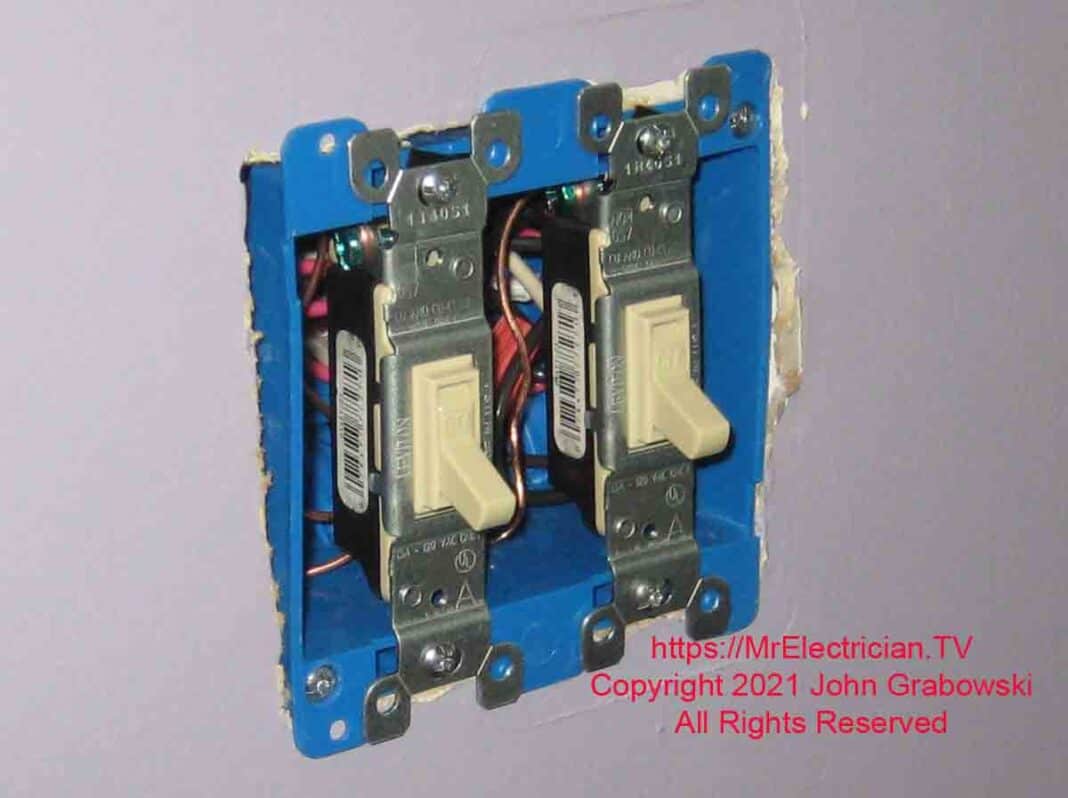
Below is an example of a ceiling fan installation I did for a client. I converted the existing single wall switch that controlled an electrical receptacle outlet to two wall switches that now control the ceiling fan and light kit separately.
CONTROL CEILING FAN AND LIGHT SEPARATELY
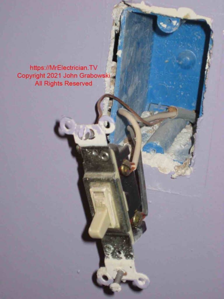
In the above switch box, the white wire is usually the hot or LINE, and the black wire is the LOAD. When the wiring is checked at the outlet, a white wire is seen connected to the hot black wires. This is normal. However, the white wire should have been re-identified with a different color because it is not a NEUTRAL conductor.
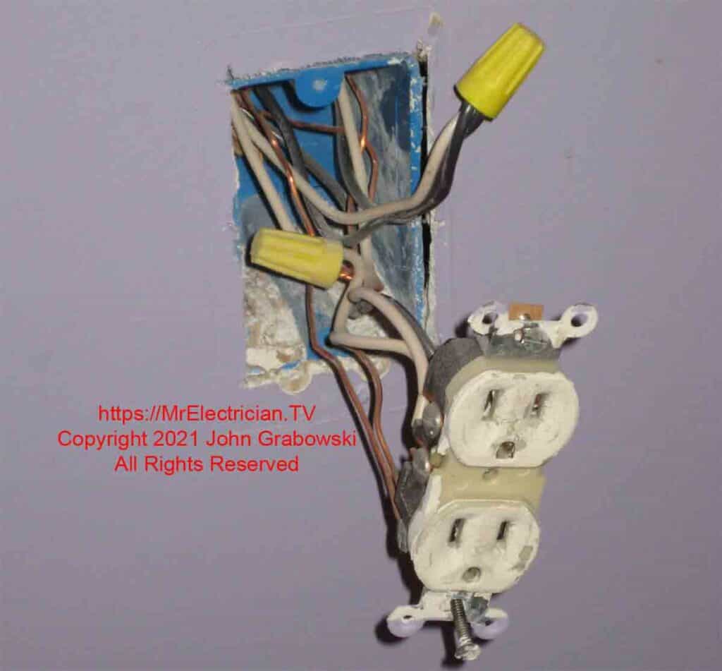
In the above photo of an electrical outlet controlled by a wall switch, notice the white wire and two black wires connected together. One of the black wires is the LINE or hot wire into the outlet box, but instead of getting terminated directly onto the outlet, it is connected to the white wire that goes to the wall switch. The white wire is the LINE hot at the switch, and the black wire is the LOAD. The white wire should have been re-identified with a color other than white, gray, or green.
The black wire from the switch box is connected to the outlet. One of the white wires connected to the outlet is the LINE neutral conductor, which is part of the same cable as the LINE black wire.
The additional white and black wires connected to the LINE hot and LINE neutral feed power to another area of the house.
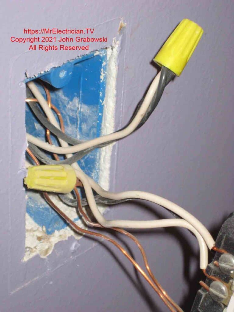
I changed the wiring connections so that the outlet was live (Hot) at all times, and the switch box now had a LINE hot and a LINE neutral. Click for my article about converting a switched outlet to hot for more details and photos about how I did this.
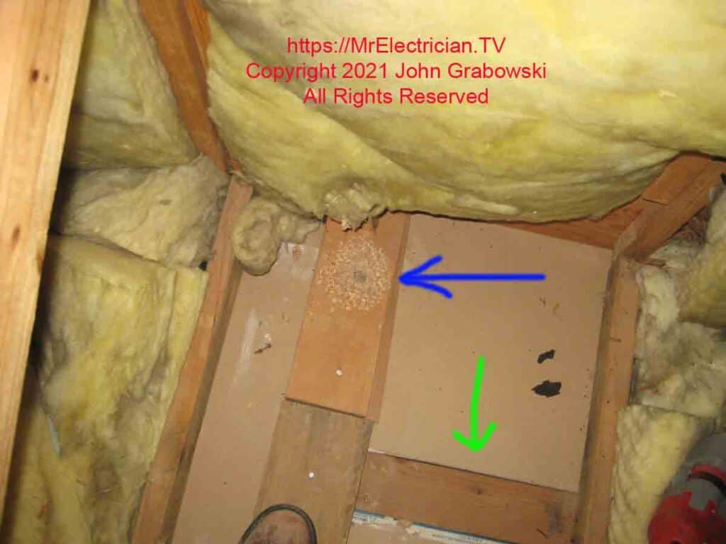
The blue arrow points to a hole that was drilled into the top plate of the wall so that a cable could be fished down to the switches. The green arrow indicates where the ceiling drywall meets the wall’s top plate.
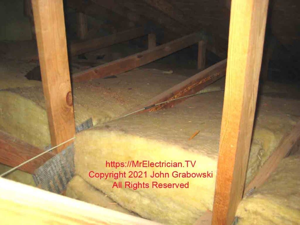
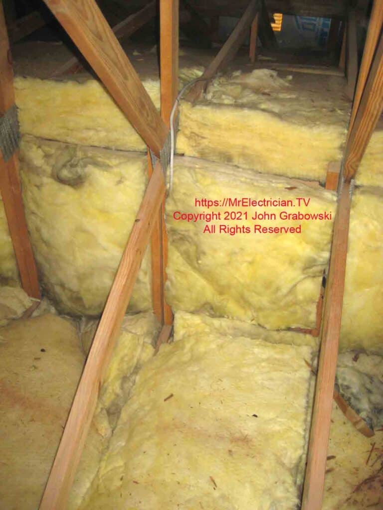
A fiberglass wire pulling rod was used to pull the 14/3 Romex cable across the attic.
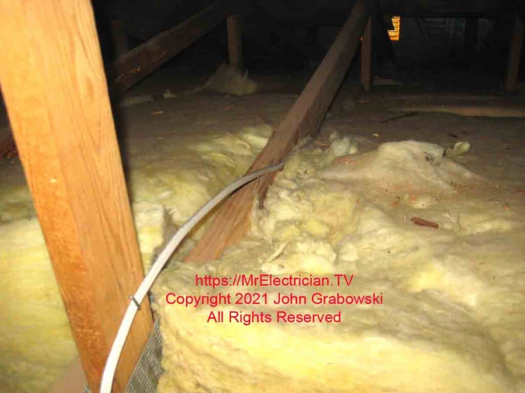
The 14/3 Type NM-B Romex cable is stapled to the side of the attic trusses.
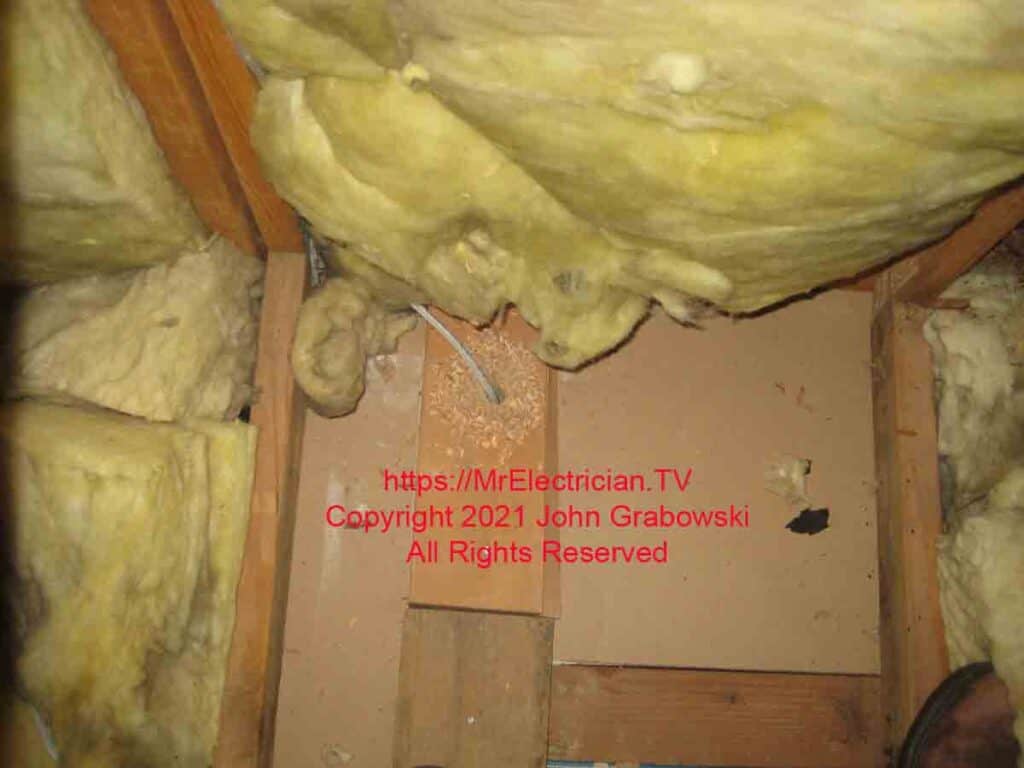
The hole in the top plate was filled in later with Firestop caulk because I didn’t want to get that stuff on my camera.
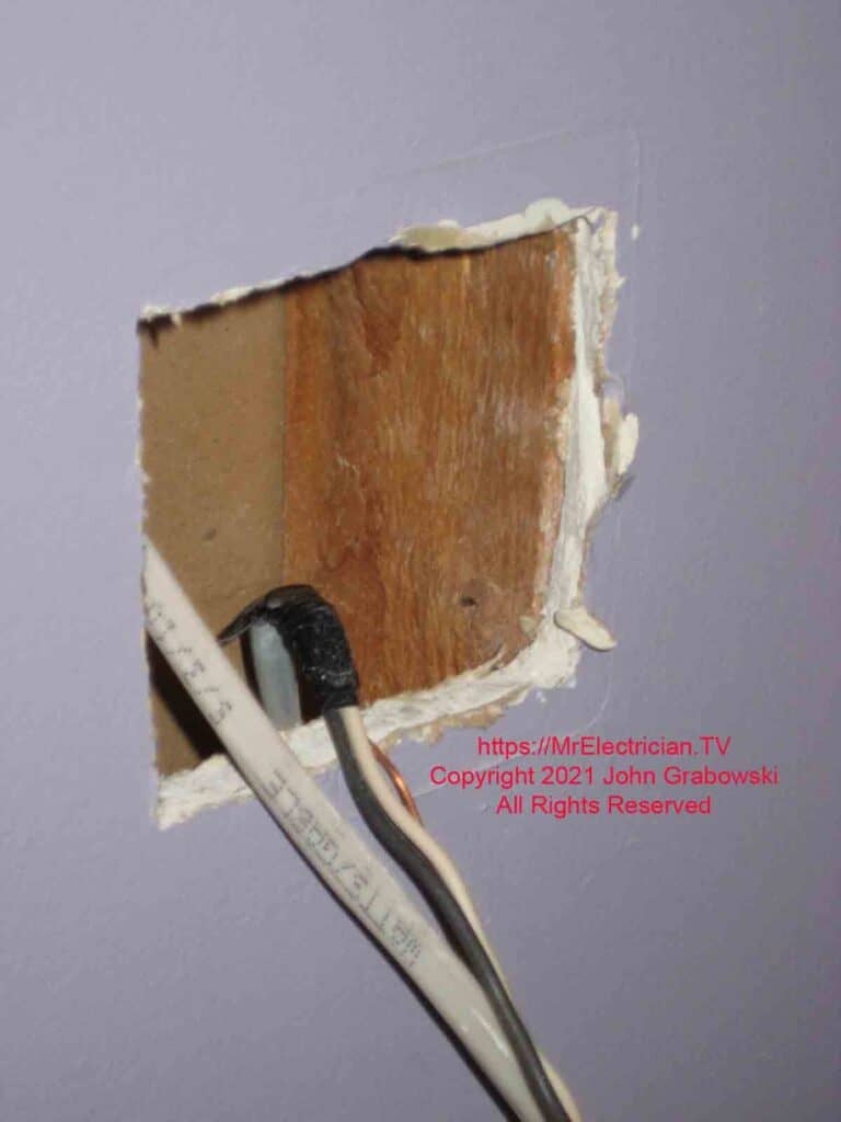
The old switch box was removed, and the existing hole in the wall was made larger to accommodate the new two-gang plastic old work electrical box.
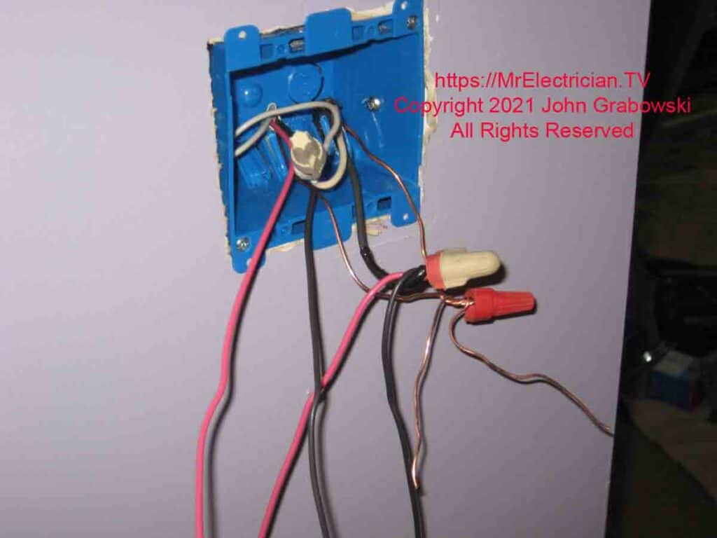
I used the excess wire from the 14/3 Romex as pigtails for the LINE connections to the switches. The 14/3 contains the light and fan LOAD wires going up to the ceiling fan.
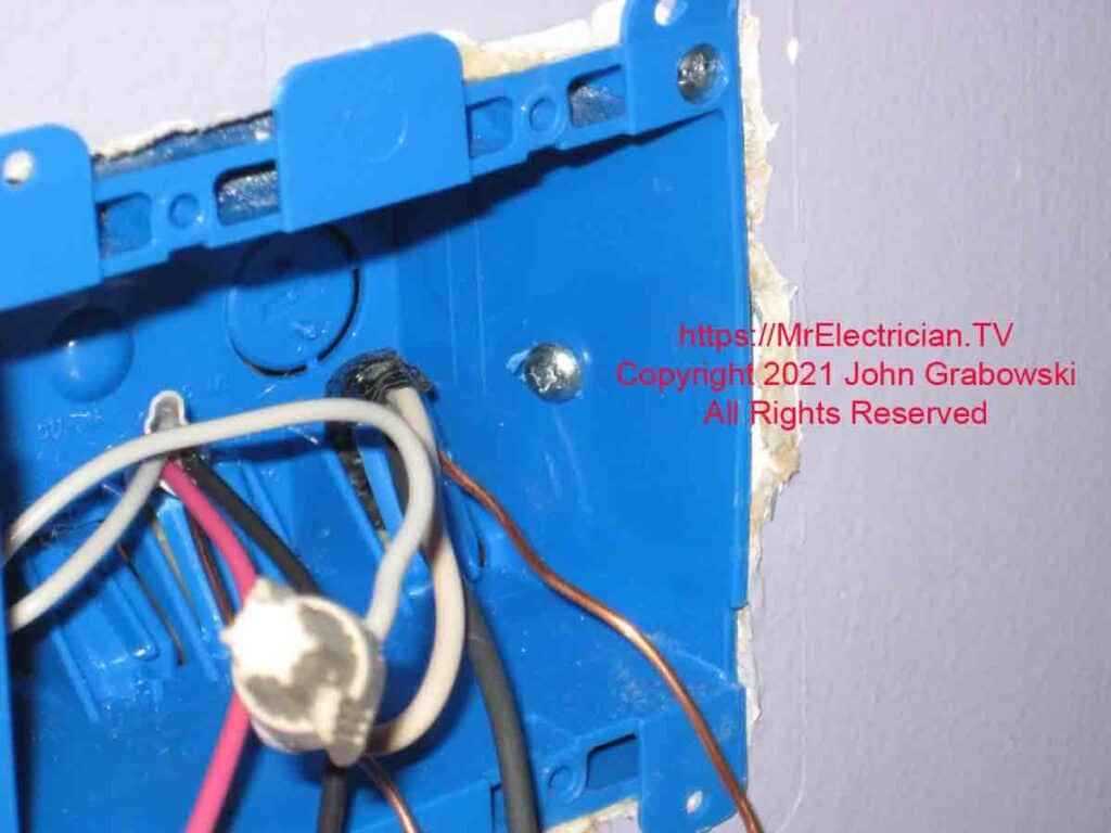
One #8 x 1 1/4″ sheet metal screw was driven through the box into the wood wall stud to secure the electrical box. Care must be taken to not over-drive the screw into the wood, distorting the electrical box.
Some electrical inspectors may consider this a code violation, but it does make the electrical box more secure over the long term.
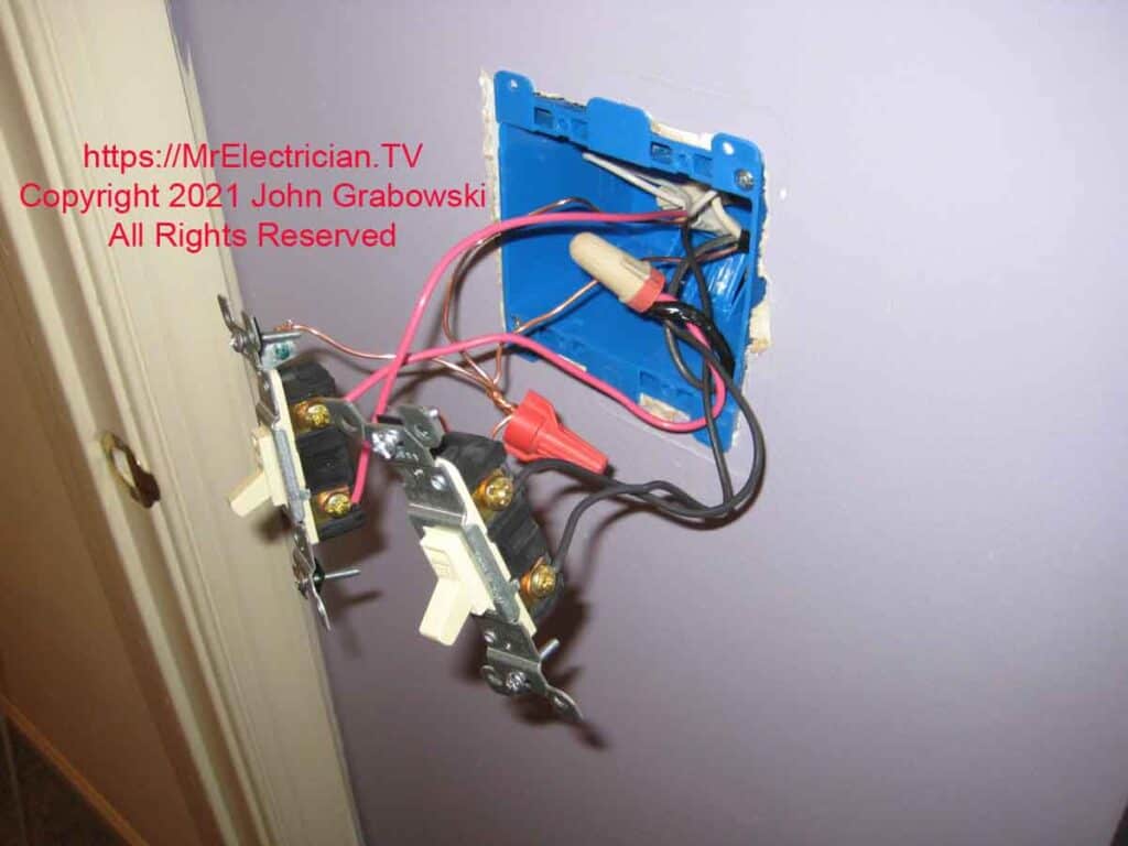
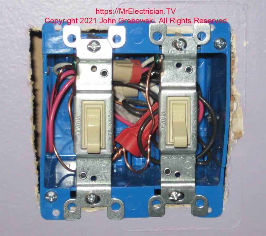
Depending on the brand and type of wall plate to be installed, removing the ears from the switches and outlets is sometimes better when installing them on plastic old-work boxes. When I install steel old-work boxes, I usually remove the ears.
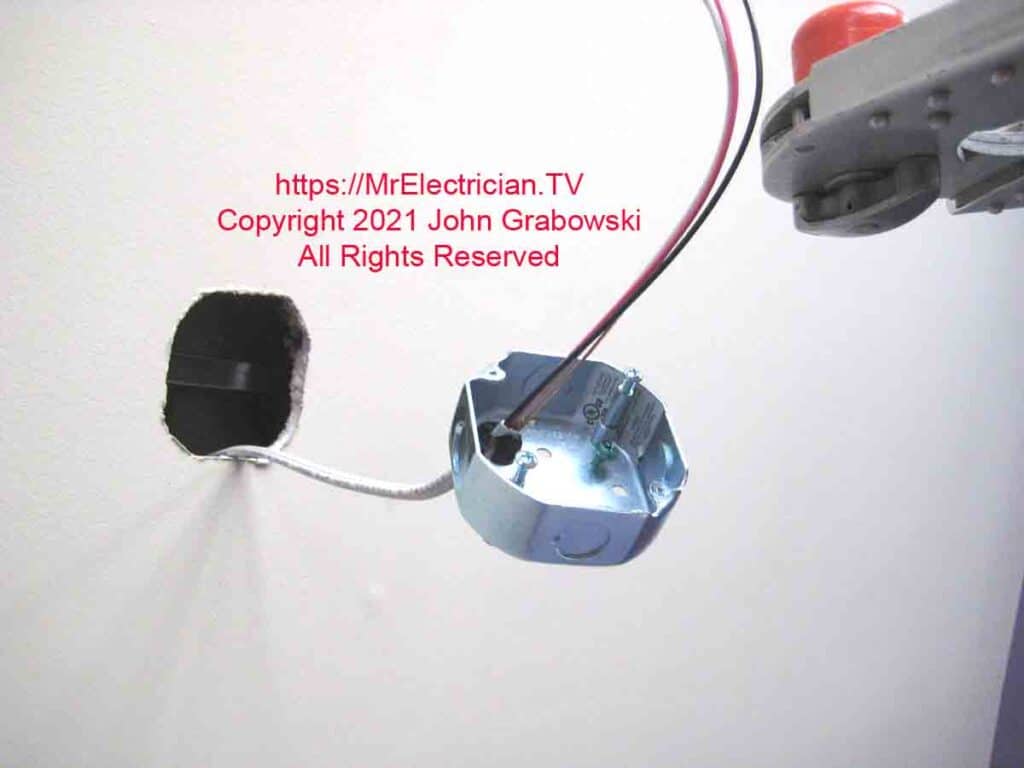
Above, the old work fan brace is installed inside the ceiling. The steel octagonal fan-rated box is ready to be attached.
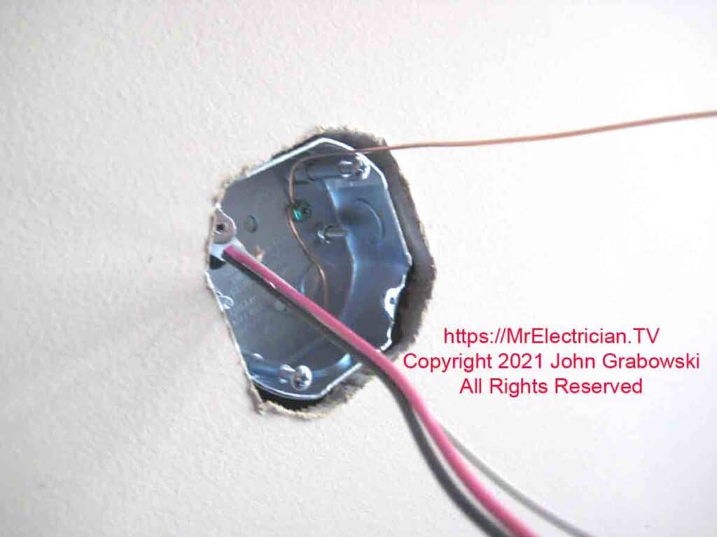
All metal electrical boxes must be grounded. Part of the grounding conductor is under the green grounding screw with the end hanging out for connecting to. The fan box above also has 8/32 screw holes for a standard ceiling light fixture to be attached.
UPDATE: Beginning with the 2020 National Electrical Code 250.148 (C), the grounding method of the metal box depicted above and below is no longer permitted. The box must now have a separate grounding pigtail connected to all the other ground wires.
CLICK HERE to see Ceiling Fans on Amazon
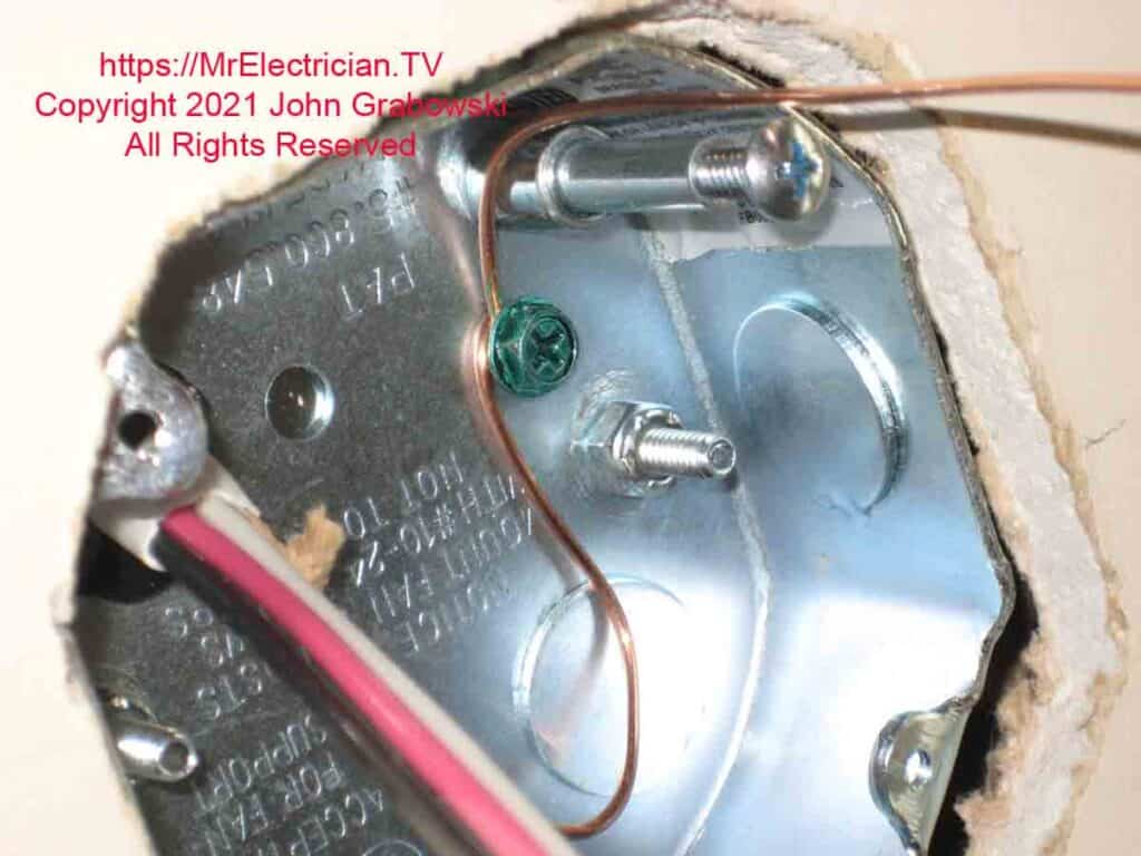
In the photo above, the box is grounded by looping the grounding conductor from the feed cable around the ground screw. This method of box grounding is no longer permitted. The box must have its own grounding pigtail. See my blog post about grounding outlets and switches for more details.
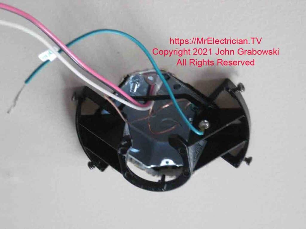
The above is one of many different styles of ceiling fan brackets that come with each fan. They are all made to be mounted onto a standard fan-rated electrical box.
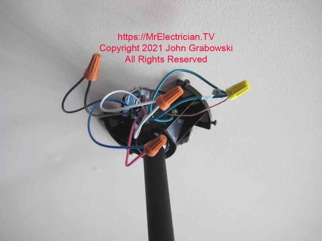
All ground wires in the ceiling fan electrical box get connected. All white neutral wires go together. If you are going to install a remote control receiver, this is where it gets inserted.
I connected the black wire from the new wall switch to the black wire on the fan that controls the fan motor. The red wire from the switch was connected to the blue wire on the fan to control the light on the fan.
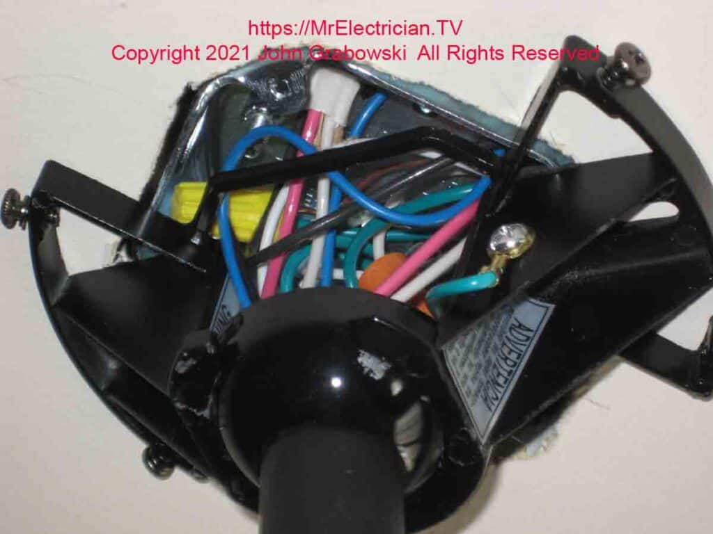
All those wires jammed inside the electrical box are a compelling reason to use a 2 1/8″ deep fan-rated electrical box instead of a box with a 1 1/2″ depth.

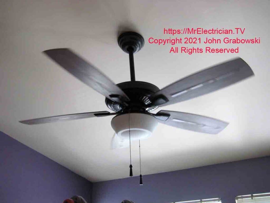
Click for my Ceiling Fan Wiring Diagrams article for several ceiling fan wall switch wiring choices.
Click here to see all of my articles concerning ceiling fans.
Look at some nice Casablanca Fans here.
Click for a FREE copy of my book “Almost Everything You Need To Know To Repair a Bathroom Exhaust Fan In Your Home.”
Get your required “Emergency Disconnect, Service Disconnect” labels and stickers to satisfy the 2023 National Electrical Code requirements in article 230.85(E)(1) and (2) by going to my Redbubble Shop here.
Visit my Link Tree home page for my social media connections and other links.
