Dear Mr. Electrician: Tell me how to install a generator interlock kit and inlet on my main electrical panel to connect a portable generator.
Answer: How to install a generator interlock kit and inlet is explained below in detail with photos. A generator interlock kit is excellent if you want to supply temporary power to your entire circuit breaker panel and can be an economical choice compared to installing a separate external transfer switch.
The interlock kit and generator inlet can be installed before you purchase a portable generator. However, it is a good idea to test the interlock kit and inlet before you lose power in your home. You can rent or borrow a portable generator for that.
NOTE: Some text links below go to applicable products sold on Amazon. As an Amazon Associate, I earn from qualifying purchases. Using my links helps to keep this website FREE.
Below are step-by-step photos depicting how to install a generator interlock kit and inlet on an older Cutler Hammer main circuit breaker panel. There are also photos and details of the power inlet installation, which is how the temporary generator power is supplied to the existing main electrical panel.
WARNING: Do not attempt to connect a portable generator to your home’s electrical system using a backfeed cord to plug into an appliance electrical receptacle. A backfeed cord, or suicide cord, is dangerous because it has a male plug at each end, which can become energized when plugged in. There is also a risk that the backfeed power from the generator is not connected correctly when plugged in this way and can damage other appliances or cause a fire.
Follow the advice below for safety. There is a short installation video at the end of this article.
Table of Contents:
- Getting the Permit for the Interlock Kit Installation
- Planning the Interlock Kit Installation
- Installing the Power Inlet
- Installing the Generator Circuit Breaker
- Mounting the Interlock Kit
GETTING A PERMIT FOR YOUR GENERATOR INTERLOCK KIT INSTALLATION
Before installing an interlock kit on your main electrical panel, you should obtain an electrical permit from your town’s building department. Submit a copy of the interlock kit installation instructions with your permit application.
In addition, I always write a short “Scope of Work” and include that with my permit applications so that the inspector clearly understands the work being done beforehand. The scope of work is no longer than one page and contains details of the work to be done and the materials used. I also include the location of the main electrical panel and the generator inlet.
For the installation depicted below, I submitted documentation about the interlock kit, the PB30 generator inlet, and my application for an electrical permit for this job. I also made a simple drawing depicting the location of the generator inlet in relation to the basement electrical panel.
Furnishing this information is helpful for the electrical inspector and lets them know if it looks like it will be code-compliant. It is better to find out beforehand if the job will pass inspection rather than fail inspection after completion.
For example, on one of my permit applications in one town, I submitted the name of the interlock kit I planned to use. The inspector contacted me and said that particular interlock kit was not approved for installation in my state. That saved me from having to do the installation over.
When the work is completed, you will arrange for an electrical inspector to review the job to ensure it complies with the electrical code. This is very important to ensure that your installation is safe and not hazardous to someone connecting the generator during a power outage.
PLANNING A MAIN BREAKER INTERLOCK KIT INSTALLATION
First, it would be best to plan your safety while installing a generator interlock kit. Use proper tools. Use the correct size ladder instead of standing on a chair, crate, or bucket. Gloves protect your hands, but you should also protect your eyes. Remove all jewelry and your watch. Wear steel-toe work boots. Tie back long hair.
If you are uncomfortable working around live electrical parts, hire a professional licensed electrical contractor. See my safety page for more information about working safely.
If you are shutting off the power while doing this work, I recommend wearing a headlamp.
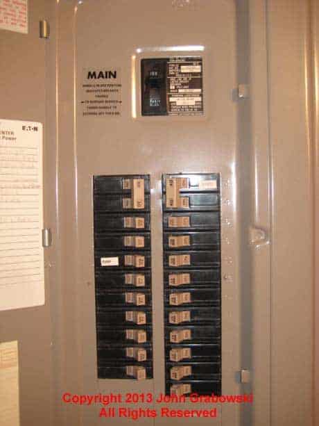
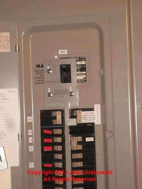
Above is what the Cutler Hammer circuit breaker panel looked like before installing the interlock kit. Fortunately, there were five available spaces in this 30-circuit panel. The interlock kit for this particular Cutler Hammer panel requires three spaces on the top right.
To install a main breaker interlock kit, you will need a few extra spaces in your main electrical panel as a two-pole 30 amp or two-pole 50 amp circuit breaker will need to be installed adjacent to the main breaker.
The new two-pole breaker will be connected to the incoming power from the portable generator. Usually, two or three spaces are required for the generator’s two-pole circuit breaker.
Main breaker generator interlock kits are available from the original manufacturer for many new electrical panels. However, using an interlock kit from a third-party manufacturer is sometimes necessary for older electrical panels.
The interlock kit depicted in the photos on this page is from a third-party manufacturer (www.interlockkit.com). A certified testing laboratory approved its use on this particular electrical panel.
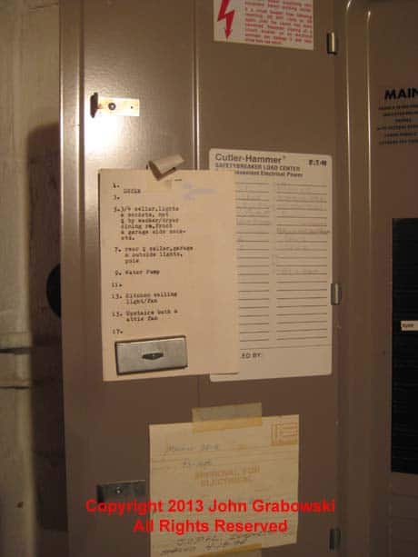
The homeowner had typed up a panel directory for most circuits years before this installation. It was handy when identifying critical circuits to run off the portable generator. A circuit tracer is handy for tracking down circuits throughout the house.
Before installing the generator interlock kit and inlet, you should identify some of the circuits you want to be powered by the generator. Circuits such as refrigerators, heating systems, and well pumps are most commonly used for generator power. You should also identify the circuits nearest the main circuit breaker, as they must be relocated to allow room for the generator circuit breaker.
INSTALLING A GENERATOR POWER INLET
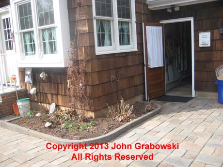
The photo above shows where the homeowner chose to have his portable generator sit and operate during a power outage. The open door is the rear entrance to the garage.

The hole in the wood siding was made using two spade drill bits. First, a 7/8″ bit was used to drill a 3/8″ deep hole to allow for the button connector. A 1/2″ drill bit was used to drill through into the basement.
Pick a location outside of your house to mount the generator inlet. It should be in a convenient area to wheel the generator over to. It should also be easy to install the permanent electrical wiring from the generator inlet to the main electrical panel.
Do not operate a portable generator near a window or inside the house, as the exhaust fumes from the generator are deadly and can kill the occupants.
CLICK HERE To See Interlock Kits on Amazon
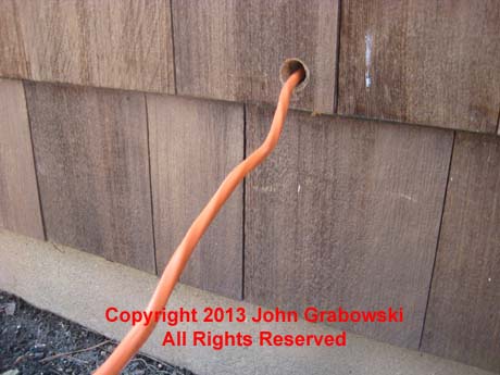
For a 30 amp generator inlet, use #10 wires in conduit or a 10/3 cable with the ground as depicted in the photo above. For a 50 amp generator inlet, use multiple #6 wires in conduit or 6/3 cable. I used two wood spade drill bits in the photo above to make the hole.
I used a larger spade wood drilling bit first and drilled into the siding approximately 3/8″ to allow space for the cable connector. Then, I drilled with a smaller bit to accommodate the wire only. A small hole will keep rodents out and outside air out.
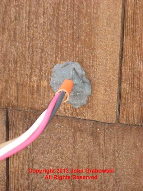
After pulling the wire through the hole and stripping it back, push the duct seal into it and leave a small mound on the surface. The cable connector will push into this and make a tight seal. If you use a button-type cable connector, you would attach that to the inlet box first and pull the wire through.
If you use a two-screw Romex-type connector, you will first put that on the cable after removing the locknut. Do not over-tighten the clamp screws, as that could cause the wires to short-circuit each other.
I usually cut the clamp screws short after attaching the connector using my Knipex High Leverage Diagonal Pliers or Klein Lineman Pliers. This makes it easier for the cable connector to fit into the hole in the house that the cable is coming through.
Remove the 1/2″ knockout on the back of the generator inlet box and bring the wire through the hole. 1/2″ is the trade size, and the actual diameter is approximately 7/8″. When the threads of the Romex connector come through the hole, screw the locknut back on tightly.
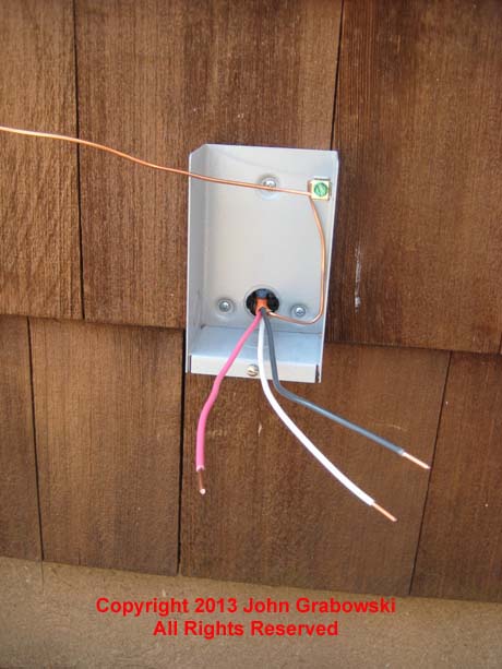
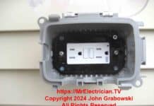
A button-type Romex connector was used above to prevent the 10/3 Romex from being pulled out. The generator inlet box was secured to the wood siding using #8 x 1-1/2 inch pan-head sheet metal screws.
UPDATE: Since this installation was completed, the design of the 10/3 Romex cable has changed. It is now flat instead of round. Consequently, using a 3/4″ Romex connector or button would be best.
Now, you can attach the generator inlet box to the house. I use #8 or #10 sheet metal screws for a wood or vinyl siding house. For a solid masonry house, I use plastic anchors with #12 sheet metal screws.
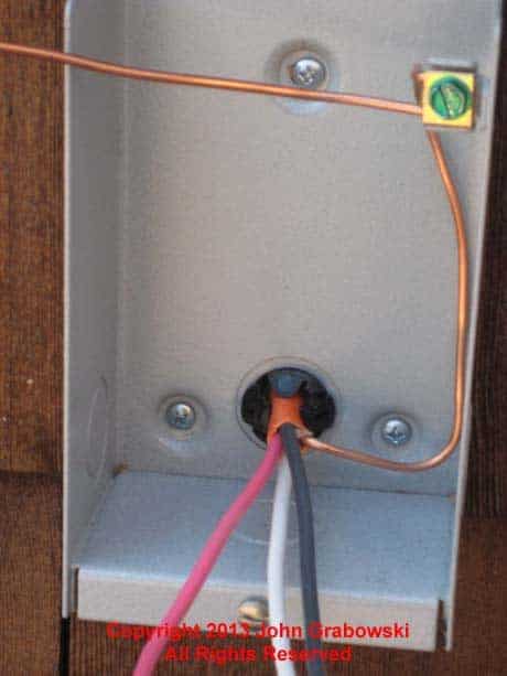
Note how the number 10 bare copper ground wire is shaped in the rear of the generator inlet box and then wrapped around the green ground screw using the included clamp.
