You are on Page 3 of “How To Install a Generator Interlock Kit and Inlet.” Click here to go to Page 2
Table of Contents:
- Getting the Permit for the Interlock Kit Installation
- Planning the Interlock Kit Installation
- Installing the Power Inlet
- Installing the Generator Circuit Breaker
- Mounting the Interlock Kit
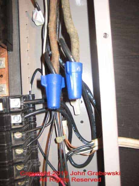
Above is a close shot of two Ideal 30-454 Wing-Nut Blue Wire Connectors to splice short pieces of #8 copper wire to the existing stove feed wire. This was necessary to relocate the existing stove circuit breaker down a few spaces to make room for the generator circuit breaker.
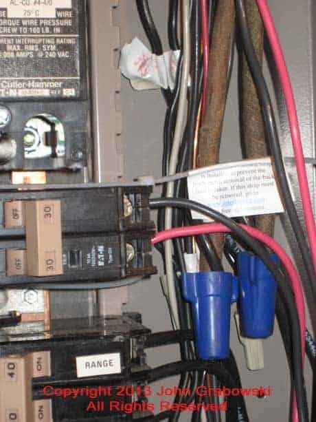
The generator circuit breaker above with the cables attached. The empty circuit breaker space below the two-pole 30 amp generator breaker is needed to operate the interlock kit.
Note the label above the Ideal 30-454 Wing-Nut Blue Wire Connectors. It is attached to a strap holding the generator circuit breaker in place and is required per the interlock kit instructions. This interlock kit installation would have failed the electrical inspection without the label attached.
It is essential to follow the instructions that come with the interlock kit. This will ensure a safe operation, code compliance, and pass an electrical inspection.
An inexpensive circuit tracer is helpful when identifying essential circuits before you need to turn on the generator. You could flip the circuit breakers off and on to see what lights and appliances stop working.
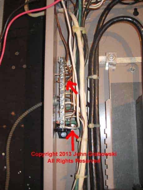
The upper red arrow points to the generator ground connection. The lower red arrow indicates the white neutral wire connection. This is the main electrical panel, so the ground and neutral are connected on the same terminal bar.
In a sub-panel, the ground and neutral would be kept separate. Only a generator with an unbonded internal neutral/ground can temporarily power this house.
Not all portable power generators are the same. A generator used to power a house must NOT have an internal neutral/ground bond. The main electrical panel already has a neutral/ground bond where the neutral and ground are connected.
A portable generator with an internal neutral/ground bond is only used in areas where the generator is the sole power source, such as a remote construction site.
The generator must have a 30 amp L14-30 twist lock receptacle on it. For a 50 amp installation, the generator must have a 14-50P 120/240 volt straight receptacle on it.
Some lower-wattage portable generators only have an L14-20R receptacle on them. Whenever a homeowner had one, I would make up a short adapter cord using an L14-20P plug and an L14-30R female connector to convert from 20 amps to 30 amps. They would be ready to go if they bought a new generator with a 30-amp output.
MOUNTING THE INTERLOCK KIT ON THE ELECTRICAL PANEL COVER
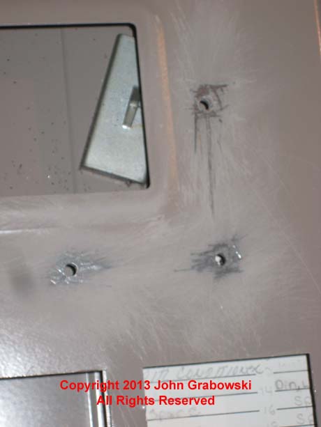
The photo above depicts the holes in the circuit breaker panel cover made using the included drill bit. It is also required to scrape and file the perimeter of the holes so that the screws can make good contact for the grounding of the interlock kit.
The drilling of the holes to mount the interlock kit onto the electrical panel cover must be precise. The manufacturer of this particular interlock kit provided a drill bit for that very reason.
Getting the holes in the exact location specified in the instructions is essential. I use the interlock kit as a template to mark the hole locations. The area around the drilled holes must be scraped or sanded to bare metal to maintain grounding continuity onto the interlock kit.
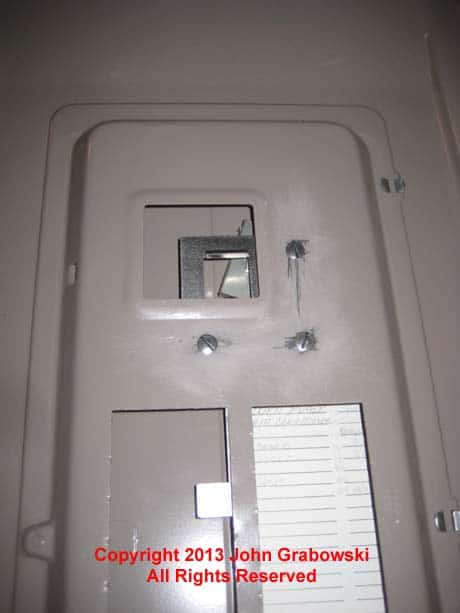
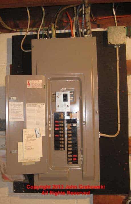
Above is the completed interlock kit installation on an older Cutler Hammer CH circuit breaker panel (Also known as a Load Center). The interlock kit functions as a transfer switch without having to install a separate box with additional wiring that requires additional wall space.
A Cutler Hammer blank panel seal was installed in the empty circuit breaker space below the generator’s two-pole circuit breaker. The blank space is needed for the interlock kit’s freedom of movement.
This interlock kit installation took me approximately four hours to complete with all materials and needed tools on site. I also spent another four hours on the initial meeting with the client, preparing and mailing the estimate, receiving and depositing the first payment, applying for the electrical permit, purchasing materials, and arranging the final inspection.
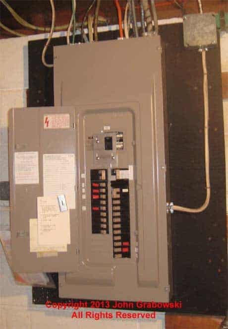
The red tape marks are on some circuit breakers so the homeowner can quickly identify critical circuits requiring generator power. These include the heating system, the electric well pump, and the refrigerator. The bathroom and kitchen lighting circuits are also identified.
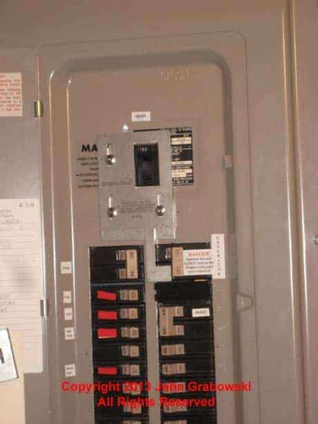
The photo above shows the completed installation of an interlock kit on a Cutler Hammer Circuit Breaker Panel. The interlock kit prevents the generator circuit breaker in the upper right column from being “On” at the same time as the main circuit breaker. Labeling is integral to the installation and must be in place to pass inspection.
In this installation, the interlock kit can get pushed down after the main circuit breaker is pushed off. Once down, the generator circuit breaker can be safely turned on. This operation prevents generator power from being on simultaneously with the utility company’s power.
The final connection is made using an L14-30 generator cord to connect the portable generator to the generator inlet. The female end of the generator cord is connected to the generator inlet. The male end is plugged into the twist-lock receptacle on the generator. This should be done with the circuit breaker on the generator in the “Off” position for safety.
Once the generator cord is connected and the generator is running, you can turn on the generator circuit breaker and then go inside the house to the main circuit breaker panel to shut off the main circuit breaker and each branch circuit breaker.
Then, turn on the generator circuit breaker in the main panel and turn on the circuits you previously chose to be powered by the generator. Of course, the beauty of the interlock kit is that you can pick and choose what circuits to turn on as needed and turn off when not required.
For a 50 amp portable generator connection, a 14-50P to CS6364 power cord would be used.
Click this link for an interlock kit installation on a GE electrical panel with a new sub-panel added.
My YouTube video of this interlock kit installation
Click to see all of my generator hook-up articles.
To help keep this website free, please use this Amazon link for your purchases. As an Amazon Associate, I earn from qualifying purchases.
Join my mailing list and receive a FREE copy of my book “Almost Everything You Need To Know To Repair a Bathroom Exhaust Fan In Your Home.”
Get your required “Emergency Disconnect, Service Disconnect” labels and stickers to satisfy the 2023 National Electrical Code requirements in article 230.85(E)(1) by going to my Redbubble Shop here.
Visit my Link Tree for more free electrical information and some unique products.
