Dear Mr. Electrician: How can I install a GE Interlock Kit on a GE main breaker panel to connect a portable generator to it safely?
Answer: To install a GE interlock kit on a main breaker, You first must determine if you have the needed circuit breaker spaces for a generator circuit breaker and interlock kit in your main electrical panel.
NOTE: Some text links below go to applicable products on Amazon. As an Amazon Associate, I earn from qualifying purchases. Using my links helps to keep this website FREE.
Table of Contents:
- Choosing An Interlock Kit
- Electrical Permit Application
- Space Avaialble for an Interlock Kit
- Adding a Sub-Panel
- A Completed Interlock Kit Installation
Usually, two, but sometimes three circuit breaker spaces are needed to accommodate the interlock kit. It varies according to the interlock kit and the circuit breaker panel.
CHOOSING AN INTERLOCK KIT FOR THE MAIN BREAKER
Some existing circuit breakers near the main will need to be moved to make room for the generator breaker. Then, you need to order the correct approved generator interlock kit for your circuit breaker panel.
On newer electrical panels, many manufacturers make an accessory interlock kit. If you read the labeling inside of the panel carefully, you should see a part number for the interlock kit for your panel. You may need a magnifying glass to read the label.
If your main circuit breaker panel is older, you might be able to obtain a third-party manufacturer interlock kit. The interlock kit shown in this post was made and sold by InterlockKit.com. The photos below depict the interlock kit installation onto a GE main circuit breaker panel installed in the 1980s.
ELECTRICAL PERMIT
Before installing an interlock kit on an existing main electrical panel, you should apply for an electrical permit at your local building department. Include a copy of the interlock kit installation instructions with your permit application. I always include a brief one-page description of the work to be done with my permit applications if I cannot fit all of the information on the permit application form.
Wording such as “Electrical work consists of installing a third party manufactured interlock kit on an existing 150 amp, 30 circuit GE main electrical panel. A new 50 amp sub-panel is to be installed for relocated circuits. Generator inlet to be installed outside next to garage door” is something that I probably used with the permit application for the installation depicted in this post.
I had a permit application for an interlock kit installation rejected once. After I submitted the paperwork, I received a call from the electrical sub-code official. He said the state was no longer accepting the laboratory testing results of the third-party interlock kit. Consequently, I could not install that particular interlock kit as it would never pass inspection.
I contacted the manufacturer, and it was confirmed that my state was the only one that was no longer accepting the laboratory testing results from this one particular testing laboratory. The testing laboratory had stopped doing electrical testing, but their previous tests were good.
My state would no longer accept even the previously accepted testing. The manufacturer said they were paying to have all their products retested by another testing laboratory that my state would accept.
The interlock kit installation below was installed before the state denied the use of this brand until they were retested.
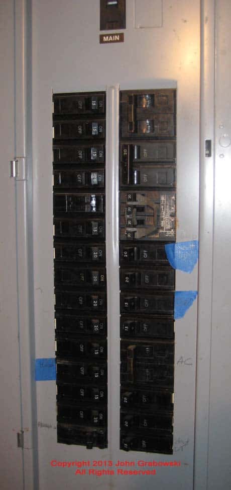
Three circuit breaker spaces in the top right side position are required for an interlock kit for the above GE circuit breaker panel.
ROOM FOR AN INTERLOCK KIT
When I first saw this client’s main electrical panel, I immediately noticed it was overloaded with circuits. The panel was only rated for 30 circuits, but due to the use of twin circuit breakers, it contained more than 30 circuits. The homeowner wanted an interlock kit installed to use his portable generator to power specific circuits in his house in the event of a utility company power failure.
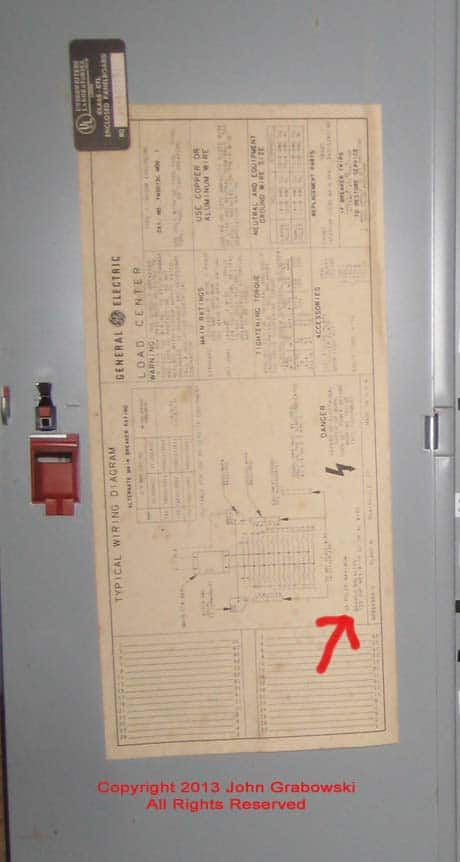
The red arrow above indicates on the GE circuit breaker panel label that it is approved for a maximum capacity of 30 circuits. It reads “30 Poles Maximum”. To comply with the “National Electrical Code,” some existing circuits needed to be removed from this panel as it already had more than 30.
By removing circuits, room is made for the three spaces needed for the interlock kit, and also brings the circuit breaker panel back into code compliance to pass inspection.
Adding a generator circuit breaker with the interlock kit in this particular GE load center required three circuit breaker spaces. To pass inspection, a sub-panel needed to be installed so that some of the circuits in the main panel could be removed and relocated. Consequently, I also needed two additional circuit breaker spaces for the main circuit breaker for the sub-panel.
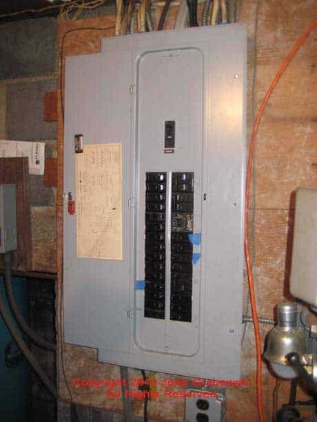
Above is what the circuit breaker panel looked like before any changes were made. The orange 10/3 Romex cable hanging down on the right side of the circuit breaker panel is the feed from the portable generator inlet box, which is mounted outside the house next to the garage.
I had to locate the new electrical sub-panel several feet away from the main panel due to a lack of space next to the main panel. It worked out well using an EMT conduit to feed the sub-panel and to relocate the existing circuits. You can see my post on electrical conduit types here.
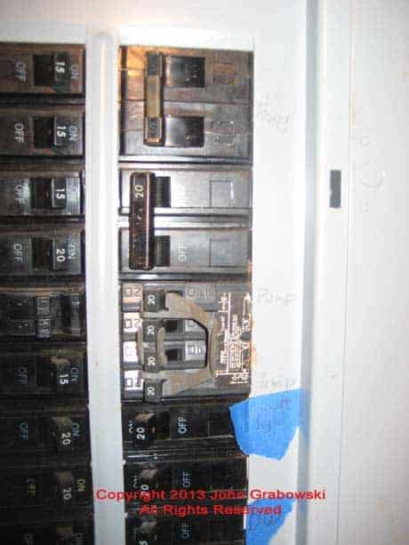
The two-pole 30 amp generator circuit breaker must be located in the two upper right circuit breaker slots near the main circuit breaker. One additional blank space is required for the operation of the interlock kit. A blank GE circuit breaker filler plate was used to fill in the empty circuit breaker slot.
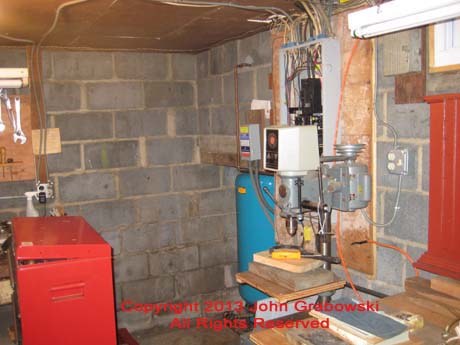
I had plenty of wall space and ceiling space to relocate some of the existing circuits and mount the new sub-panel.
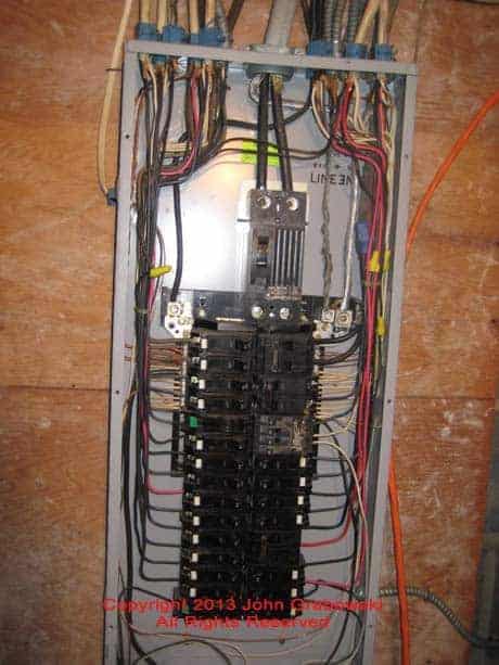
It is essential to identify the circuits you will use the generator for. You don’t want to overload the generator. With the GE interlock kit, you can choose which circuits you want to use at different times of the day.
Most people want the refrigerator, furnace, and well pump connected to the generator. Other circuits such as bathroom lighting, water heater, microwave oven, stove, and sump pump are suitable for temporary power generation during a blackout.
ADDING A SUB-PANEL
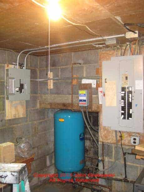
Above is the new sub-panel installed using 3/4″ EMT conduit. A 3/4″ EMT bender was used to bend the conduit to fit into place. Pre-bent conduit elbows and offset fittings are available for some sizes of electrical conduit.
Note the 4 11/16″ square junction boxes mounted on the ceiling, and by mounting the junction boxes there, removing cables from the existing GE main circuit breaker panel made it very easy to bring those circuits into the new GE sub-panel.
Some of the original circuit wiring was fastened to the drywall ceiling in this installation. I could mount two junction boxes on the ceiling and redirect a few existing circuits into the junction boxes. From the junction boxes, I pulled single conductors through the EMT conduit down to the sub-panel.
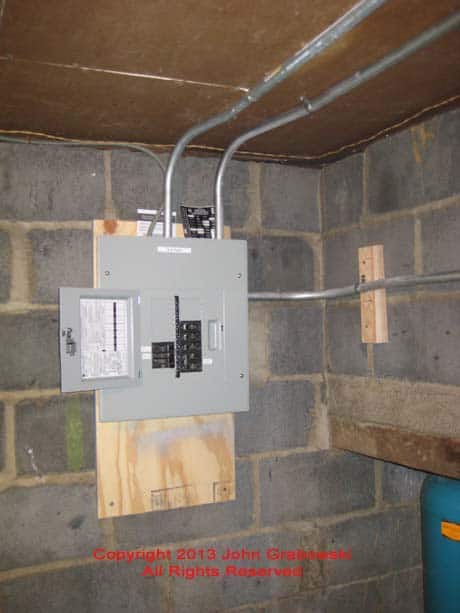
In the 3/4″ EMT conduit for the sub-panel feed from the main panel, I pulled two #6 THWN conductors for the hot LINE wires. I also pulled in one #8 conductor for the neutral and a #8 grounding conductor. A two-pole 50 amp circuit breaker was installed in the main panel for this.
Tools required for this job included a 3/4″ EMT conduit bender and a rotary hammer to drill a hole through the masonry wall to bring the 10/3 Romex into the back of the generator inlet. An electrician’s hammer, pliers, screwdrivers, awl, razor knife, half-round file, and Channellock pliers were all used here.
I used my Cordless hammer drill to make holes in the masonry to mount the sub-panel board. I used my cordless impact driver for driving screws into wood and masonry. I also used my cordless hammer drill (In drill-only mode) to make holes in the panel cover to attach the interlock kit.

Materials for this job included 3/4″ EMT conduit with set screw connectors, set screw couplings, and straps. Also used was #12 single conductor wire in white, black, and green. 10/3 Romex with a ground wire was used to connect to the generator inlet. Romex staples and BX staples were both used. #6 copper and #8 copper THWN wire were used to feed the sub-panel.
A GE sub-panel with no main (Lugs only) was used with 1/2″ and 1″ GE circuit breakers. 4 11/16″ square x 2 1/8″ deep metal junction boxes were used with Romex connectors and 4 11/16″ square blank covers. One Reliance PB30 outdoor generator inlet box was used to connect to the portable generator. Emery cloth was used to clean paint from around the drilled holes in the panel cover for better grounding of the interlock kit.
COMPLETED INTERLOCK KIT INSTALLATION
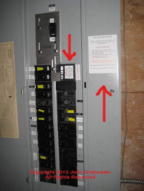
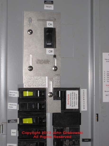
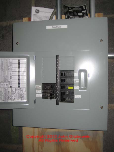
The photo above depicts a completed GE interlock kit installation with many labeled circuits. The red arrows point to labels provided by the interlock kit manufacturer and must be installed as per the instructions supplied with the interlock kit.
The yellow tape marks are there to help the homeowner choose some of the essential circuits to be powered by the generator. When the utility company’s power goes out, this basement will be dark until the portable generator is powered up.
When installing the GE interlock kit, it is essential to follow the instructions from the manufacturer. This is necessary for safe operation and also to pass inspection.
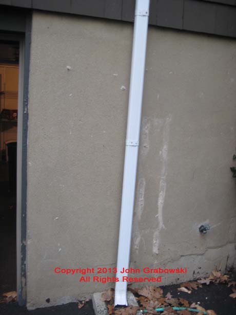
Article 445 in the National Electrical Code covers generators. You should also read article 702, entitled “Optional Standby Systems.” Article 250 is also applicable, and others may be contingent on the type of wiring methods used.
Locate the generator inlet where it is convenient to roll the generator and is not near any windows. You don’t want carbon monoxide getting into the house.
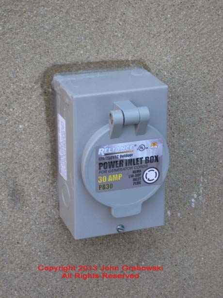
Using an L14-30 generator cord, you connect the cord to the generator inlet and to the generator before starting the generator and with the circuit breaker on the generator in the off position. The main breaker in the main electrical panel must be turned off. All branch circuit breakers must be turned off.

Turn off the main circuit breaker. Start up the generator and then turn on the circuit breaker on the generator. Then, turn on the generator circuit breaker located in the main electrical panel. Then, turn on your previously chosen branch circuits to be powered by the generator.
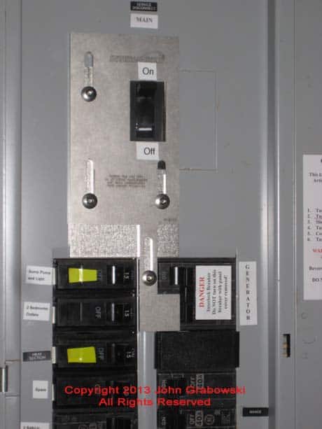
This is the completed GE interlock kit installation in the photo above. The main breaker handle gets pushed down to the “Off” position. Then, the generator circuit breaker can be pushed “On.” When the utility company restores power, the generator breaker is pushed “Off,” and the main breaker handle can be pushed up to the “On” position.
Click here for a more detailed interlock kit installation on a Cutler Hammer Load Center.
You can see photos of a Square D generator sub-panel installation by clicking here.
Click to read my article about how I wired a generator sub-panel to accommodate the homeowners’ requirements.
Click for a FREE copy of my book “Almost Everything You Need To Know To Repair a Bathroom Exhaust Fan In Your Home.”
Get your required “Emergency Disconnect, Service Disconnect” labels and stickers to satisfy the 2023 National Electrical Code requirements in article 230.85(E)(1) and (2) by going to my Redbubble Shop here.
Visit my Link Tree for social media links and merchandise. Help keep this website free.
