Dear Mr. Electrician: How do I change over my circuits to a wired generator sub-panel?
NOTE: Some text links below go to applicable products on Amazon. As an Amazon Associate, I earn from qualifying purchases. Using my links helps to keep this website FREE.
Answer: Using a prewired generator sub-panel may not suit all of your emergency power needs. Get a generator sub-panel suitable for your application. Some generator sub-panels are prewired, and you make the correct connections with the existing circuits in the main electrical panel. Those types usually have limitations regarding the number of circuits connected to the generator.
Table of Contents:
- Before Sub-Panel Installation
- Installing This Generator Sub-Panel
- Generator Inlet Installation
- Interlock Kit
- Internal Generator Bonding
Using an interlock kit, it is possible to make a generator sub-panel out of an ordinary load center circuit breaker panel. You need to get the correct accessories.
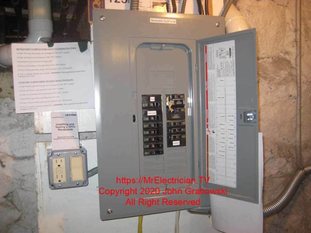
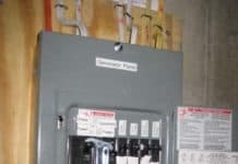
In the generator sub-panel circuit wiring installation pictured below, I used a standard Square D Type QO, 125 amp, 24 circuit, single phase load center as a sub-panel with a separately purchased Square D Interlock Kit made for this purpose.
I also had to purchase a grounding terminal bar separately for all ground wire terminations. Most load centers do not have a separate ground bar unless designated as a sub-panel. This panel did not have a main circuit breaker installed by the factory. I installed the QO 100 amp main breaker and a QO 50 amp generator circuit breaker.
For this particular generator hook-up installation, the client wanted many circuits to be powered by a portable generator. Those circuits included an electric range, electric water heater, oil burner for heat, microwave oven, bathrooms, and kitchen outlets & lighting.
My first thought was to install an interlock kit on the main breaker in the existing circuit panel that would have provided the homeowner access to all the electric circuits.
I chose to install a generator sub-panel rather than an interlock kit on the entire main electrical panel because, at the time of this installation, I could not find an interlock kit for the existing panel that the electrical inspector would approve. The panel manufacturer does not make an interlock kit for this particular panel.
There is a company called Interlockkit.com that does make an interlock kit for this main panel. However, the State of New Jersey, where this installation is located, did not accept the test laboratory certification the manufacturer used for their products.
The manufacturer has since changed testing laboratories, and some of their products have been re-tested by the new lab and are now acceptable to New Jersey. If you are in New Jersey and need an interlock kit from this company, contact the factory by phone to learn if the product you need is approved. Click to see some examples of interlock kit installations done by me.
CLICK HERE to See Generator Interlock Kits on Amazon
STEPS BEFORE GENERATOR SUB-PANEL WIRING
You need to apply for an electrical permit before wiring a generator sub-panel. When I submitted the permit application for this job, I included a copy of the installation instructions for the interlock kit, as well as the model number of the load center. I also included a typed, one-page “Scope of Work” briefly detailing the work to be done and the circuits that would be relocated.
In addition, I drew a simple diagram showing the location of the existing main electrical panel and the location of the new generator sub-panel. It is best to provide as much information as possible to help the building department understand your goals. Also, suppose there are problems with your installation methods or materials. In that case, it is best to find out beforehand rather than after the installation is completed and the inspector fails your work.
I found out about the interlockkit.com products not being acceptable because I had submitted the product information with my permit application for another generator installation job in another town. The electrical inspector called me up and told me what was going on.
I also called the factory, and they confirmed the issue. There is nothing wrong with their products, just the testing laboratory. According to the factory, their products are entirely acceptable in the other 49 states. Even so, checking with your electrical inspector beforehand is always best.
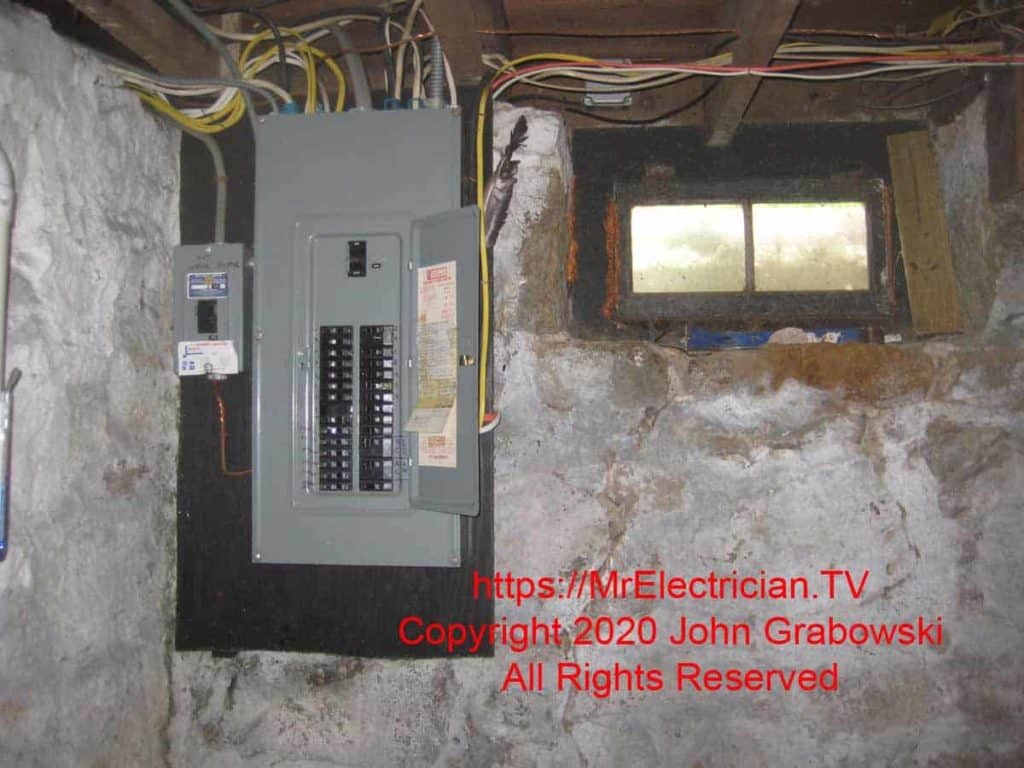
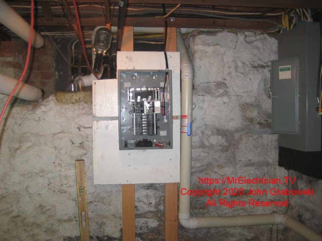
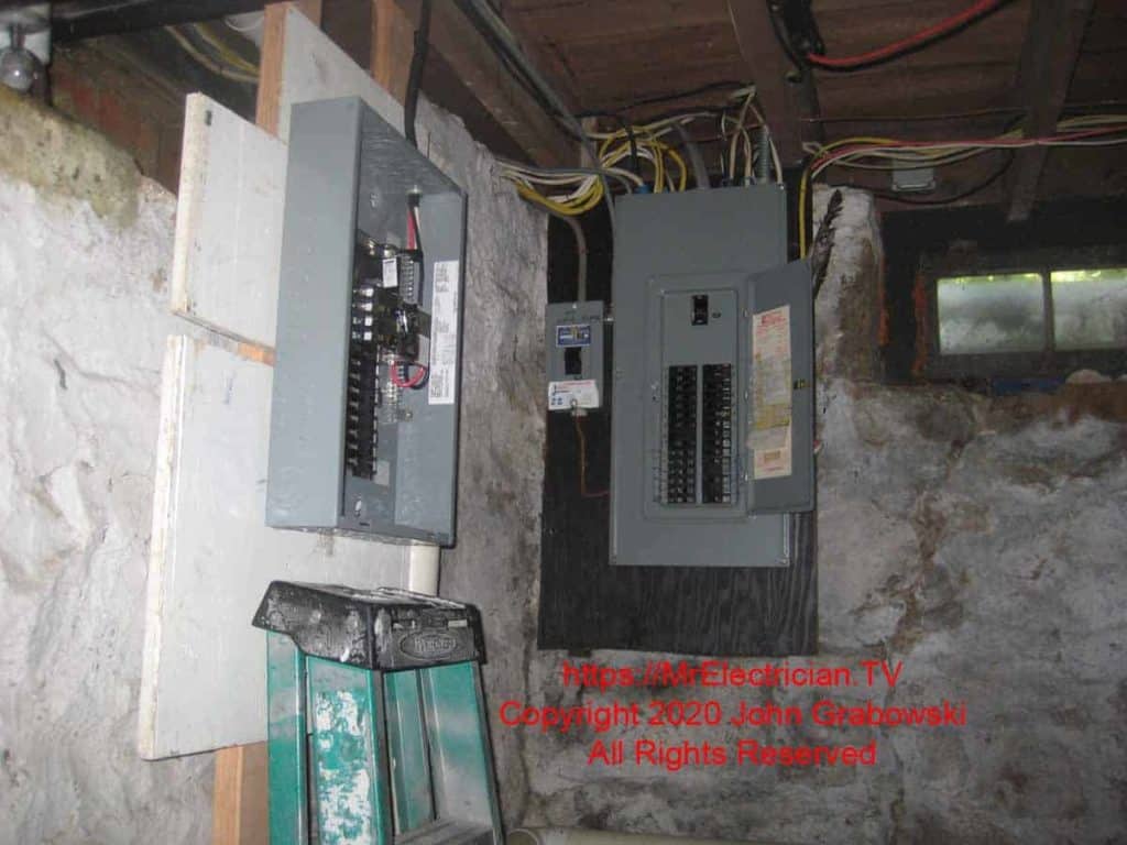
The above photo shows what was in this stone basement before any changes were made. The small circuit breaker panel to the left of the main breaker panel is not a sub-panel. It is a main panel fed from a separate electric meter exclusively for the water heater.
At one time, the power company had a program to get a reduced electric rate for the water heater if it operated at off-peak times. That program was no longer available, and I relocated the water heater circuit to the new generator sub-panel. I told the homeowner to contact the power company to get the water heater electric meter removed.
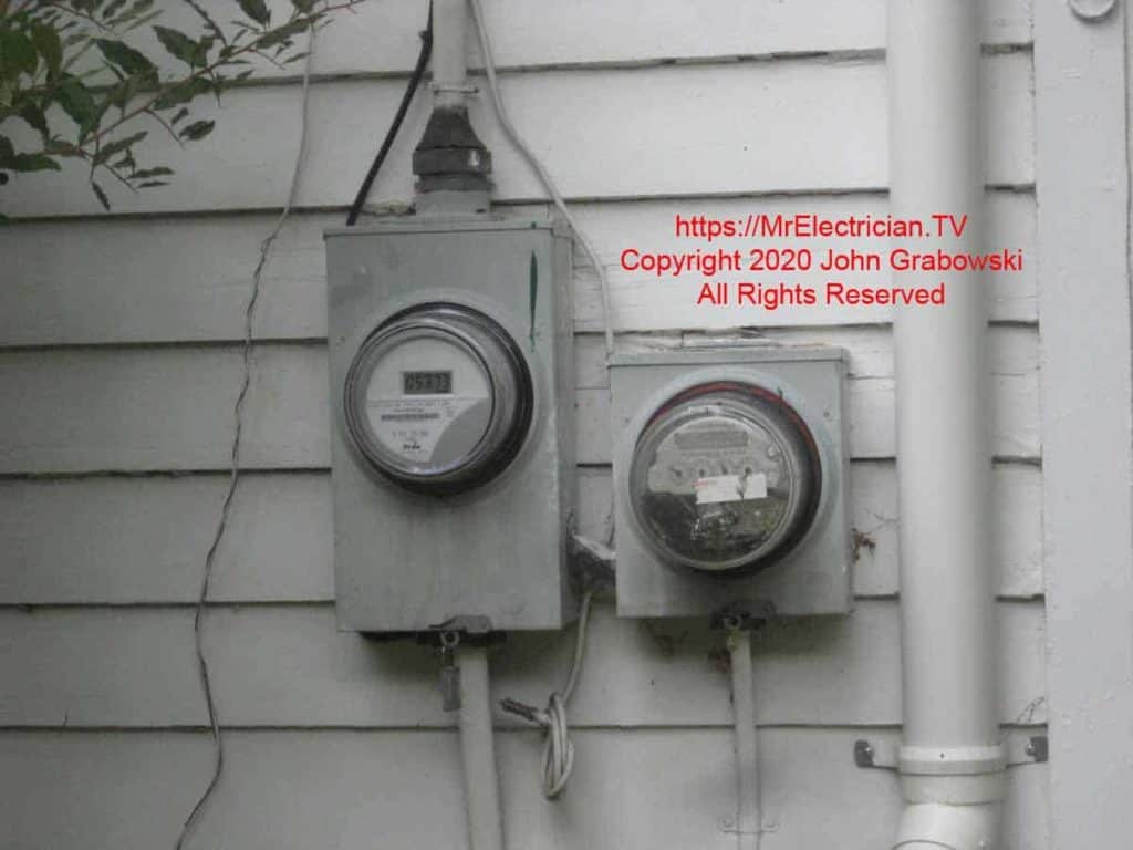
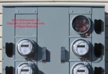
You can see on the electric meters that the smaller meter socket has a smaller wire exiting the bottom. This was the meter dedicated just for the water heater. This is not an unusual installation on older houses in New Jersey. Sometimes the smaller meter will be removed, and a meter blank will be installed after circuit wiring changes.
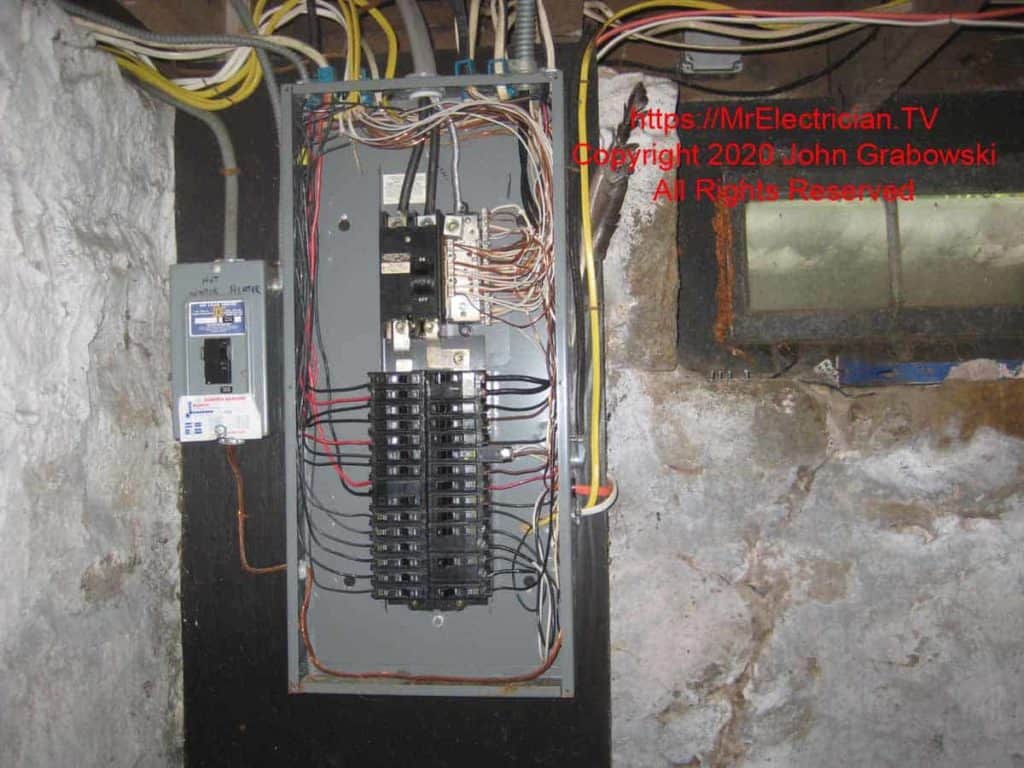
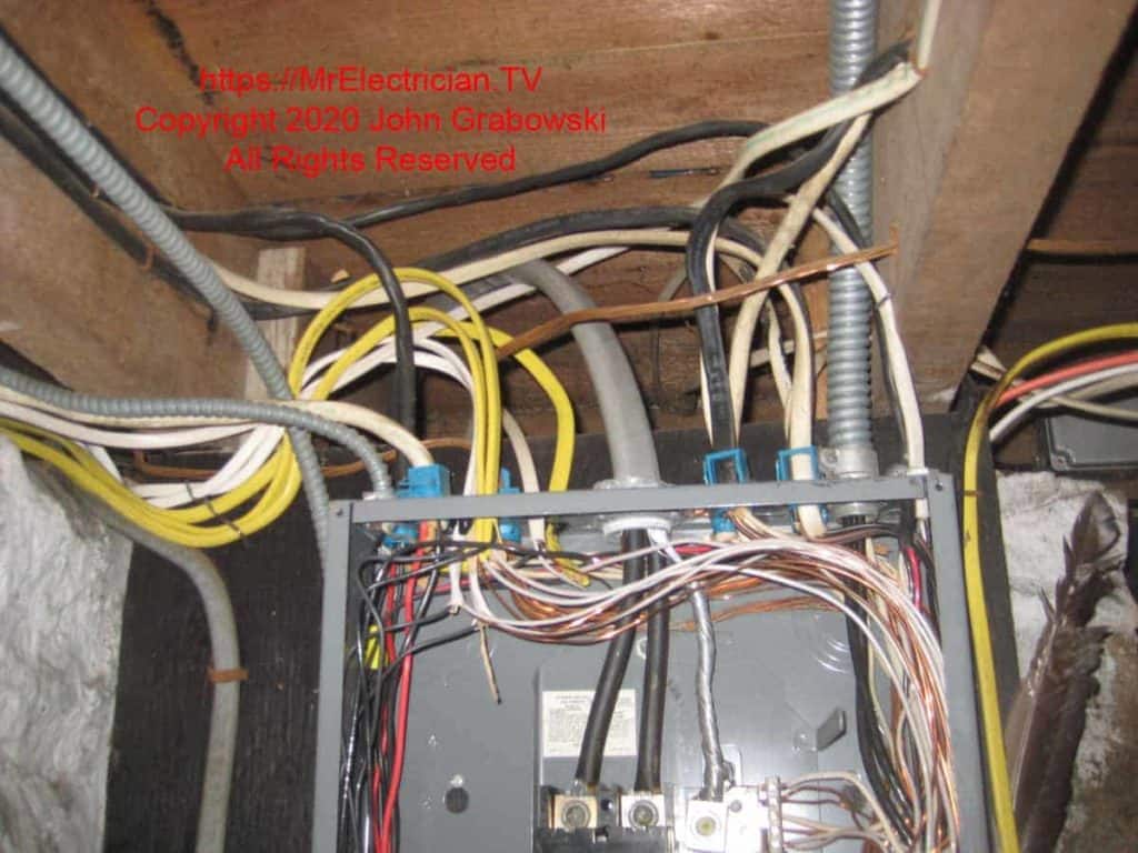
Some of the circuits above were relocated and wired into the new generator sub-panel. I used my Knipex high-leverage diagonal pliers to cut out some of those blue plastic Romex connectors. The staples were removed, and the wires disconnected so that I could easily pull back the cables for the designated generator circuits and wire them into the new generator sub-panel.
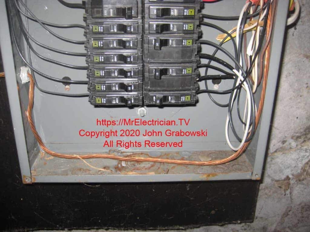
There was plenty of room at the bottom of the main electrical panel to bring in the three #3 copper conductors that feed the new generator sub-panel. A #6 green copper wire was used as the grounding conductor for the sub-panel.
The wire size for the power conductors was determined by Table 310.16 in the National Electrical Code (NFPA 70) under the 75-degree column. I used the 75-degree column because the wire insulation was rated for at least 75 degrees Celsius, and so were the terminals on the circuit breakers.
I am not aware of any terminals being rated for 90 degrees Celsius. When you doubt the temperature ratings of your wire insulation and the terminals to which the wire will be connected, use the 60-degree column.
The grounding conductor size was determined by Table 250.122, but I made it one size bigger. Some additional articles you should read are 250.34 and 702.12.
INSTALLING THE SUB-PANEL
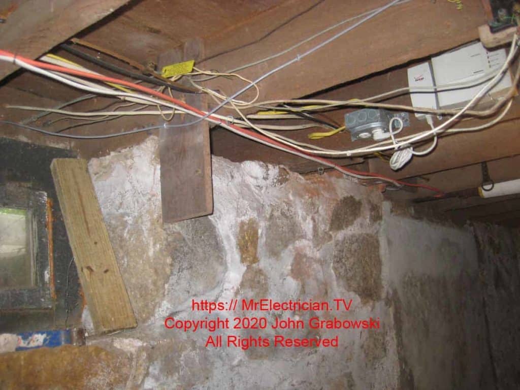
There weren’t any obstacles on the wall in the above photo to inhibit the sub-panel installation. However, it was better to locate it on the side wall because all of the circuits in the sub-panel passed overhead. It was just a matter of removing the cables from the main panel and pulling them back to the generator sub-panel location.
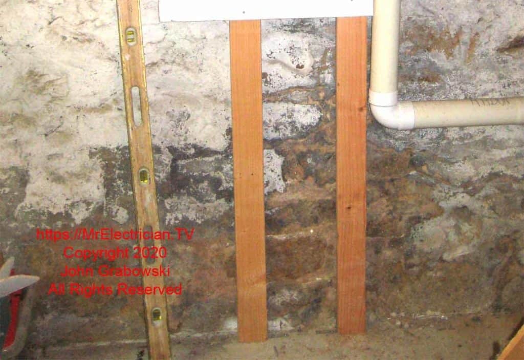
From experience, I knew it would be challenging to attach wood to the hard and uneven rock wall. My solution was to mount two separate support posts and attach my backboard.
