You are on Page 2, Click for Page 1
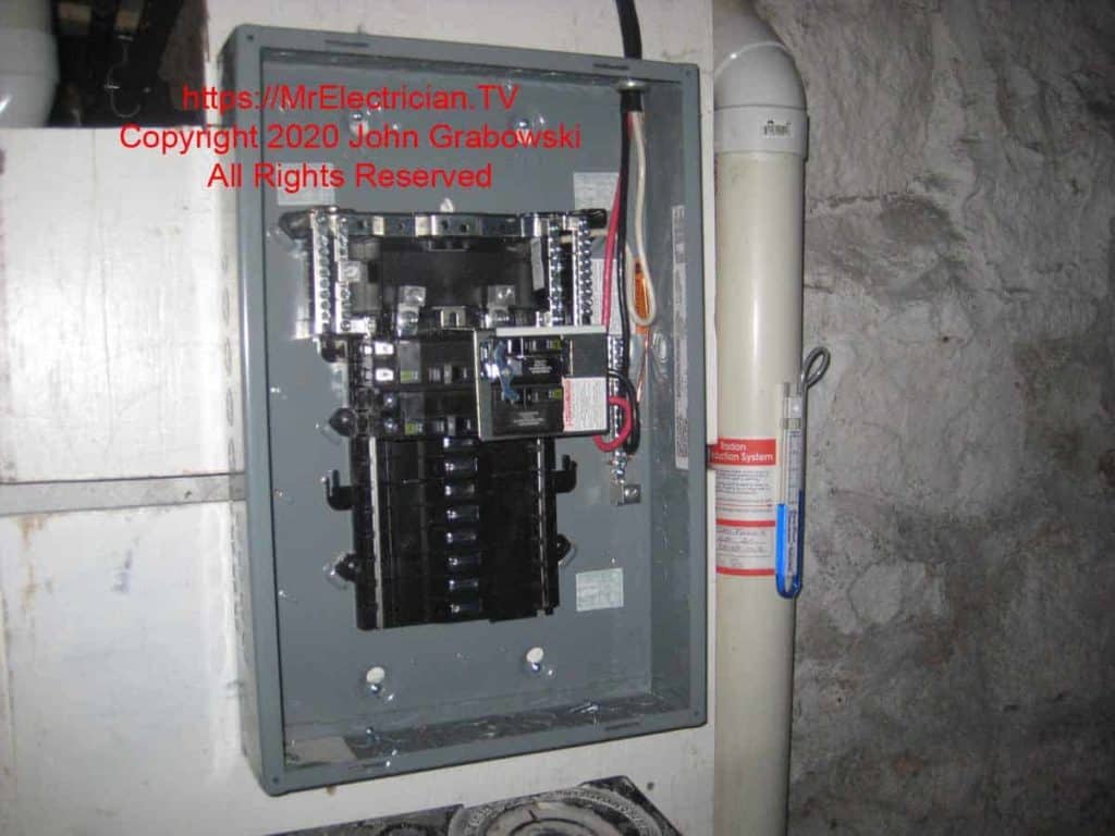
One of the obstacles that I had to overcome in this generator sub-panel installation was the existing radon exhaust pipe shown above on the right.
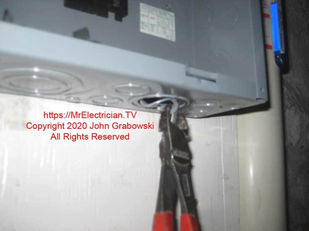
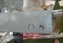
Removing the knockouts for 1 1/4″ was easy on this load center. I knocked each ring using pliers and an old screwdriver enough to stick out and then cut them with my Knipex High Leverage Diagonal Pliers. After cutting, it was just moving them forth and back to let them snap off.
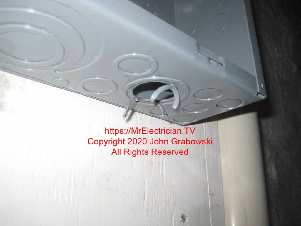
Not all knockouts are this easy to remove. It varies by manufacturer. You can see my post on concentric knockout removal by clicking here.
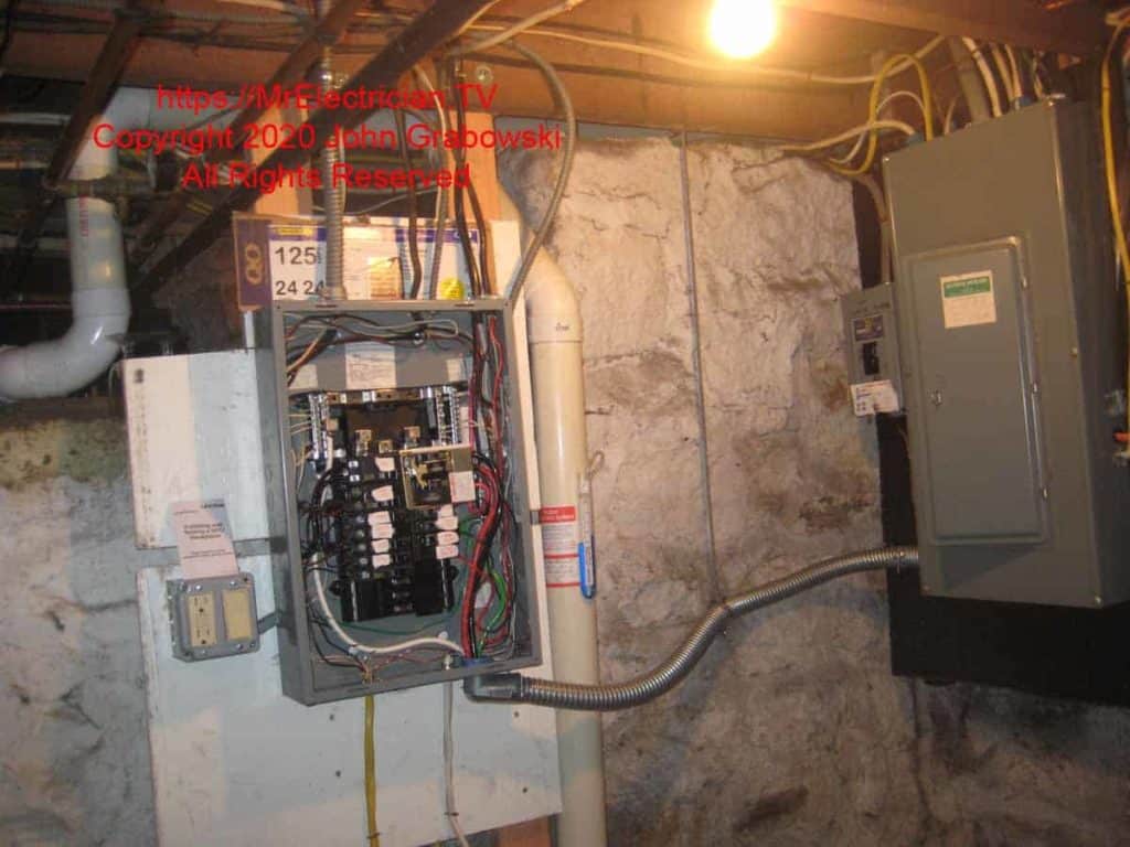
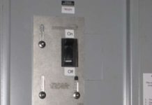
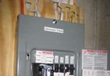
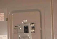
A completed generator sub-panel with the cover removed showing the interior wiring and the Square D generator interlock. A conduit hanger and threaded rod support the flexible conduit feed from the main panel.
Although there were fewer obstacles on the wall to the right of the existing main electrical panel, I chose this location because the existing circuits that would be wired into the new generator sub-panel passed overhead. Moving the circuit cables without adding junction boxes to extend the cables was easy.
Using the 1 1/4″ flexible metal conduit (FMC), I could get around the radon pipe without a problem. I used a conduit hanger and threaded rod to support the conduit from the ceiling rather than attempting to drill into the rock wall to attach conduit straps. I screwed a small L bracket to the inside of the joist and used nuts and washers to attach the 1/4″ threaded rod to the L bracket.
In addition to the hanging support, I installed a conduit hanger screwed to the wood as the FMC exited the main panel. I used the conduit hanger instead of a strap because the FMC connector was not close to the wood. The conduit hanger nearly matched the distance from the backboard and kept the conduit straight as it came out of the main panel.
Rules regarding installing flexible metal conduit (FMC) are described in Article 348 of the National Electrical Code (NFPA 70).
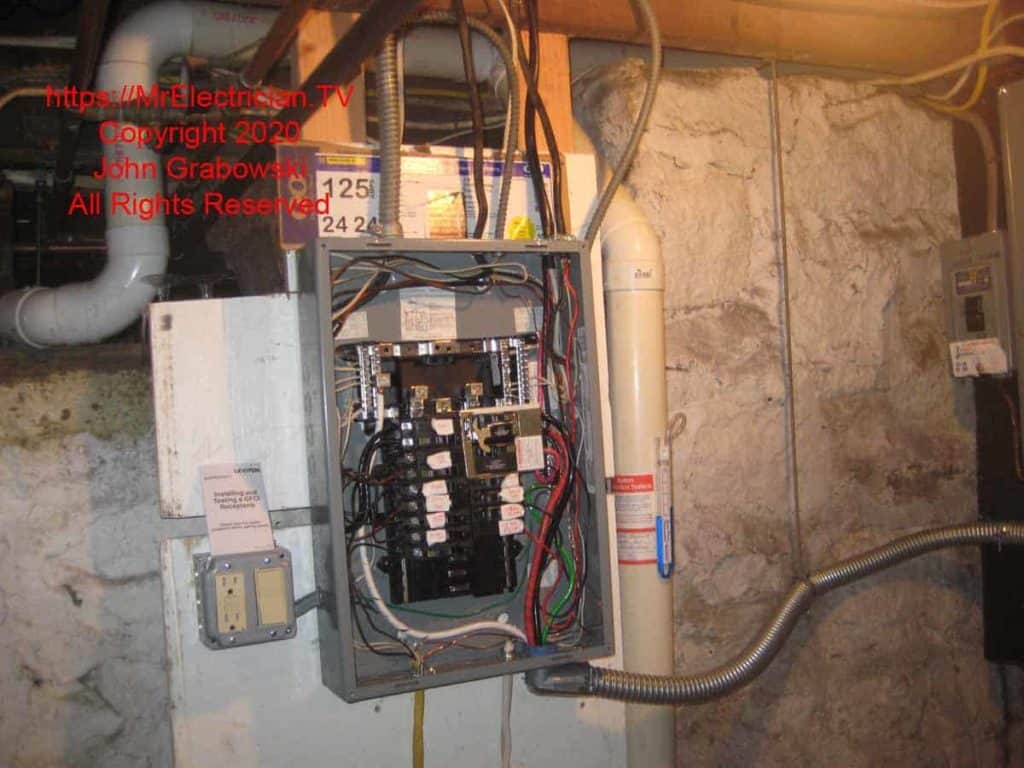
Whenever I do a basement service change or replace an electrical panel, I always add a GFCI service outlet and a light with a wall switch for illumination as required by article 110.26(D) in the National Electrical Code. I have found that it is usually dark in the basement locations of the main electrical panel.
As with all sub-panels, this one was wired with a separate equipment grounding conductor terminated on a separate ground bar terminal. Grounds and neutrals are always kept separate in a sub-panel. In contrast, the main bonding jumper connects the main panel as per articles 250.92 and 250.28 in the National Electrical Code.
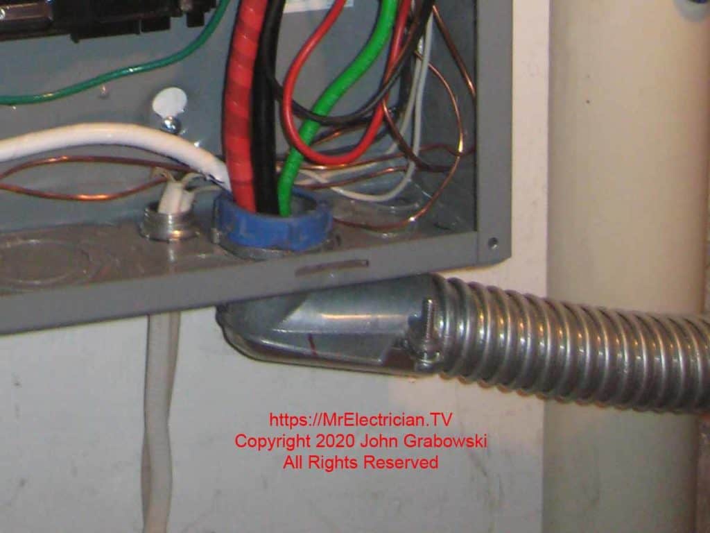
A 1 1/4″ flexible metal conduit angle connector was used to bring the flex conduit into the bottom of the sub-panel. I preferred to go into the panel with a straight connector, but the radon pipe had too much of a bulge. With the angle connector, I could rotate it a little to allow the flex to go around the radon pipe. Note using the blue plastic threaded bushing to protect the wire from sharp edges.
This wired generator sub-panel was fed from the main panel with a 100 amp circuit and fed from the generator with a 50 amp circuit.
INSTALLING THE GENERATOR INLET
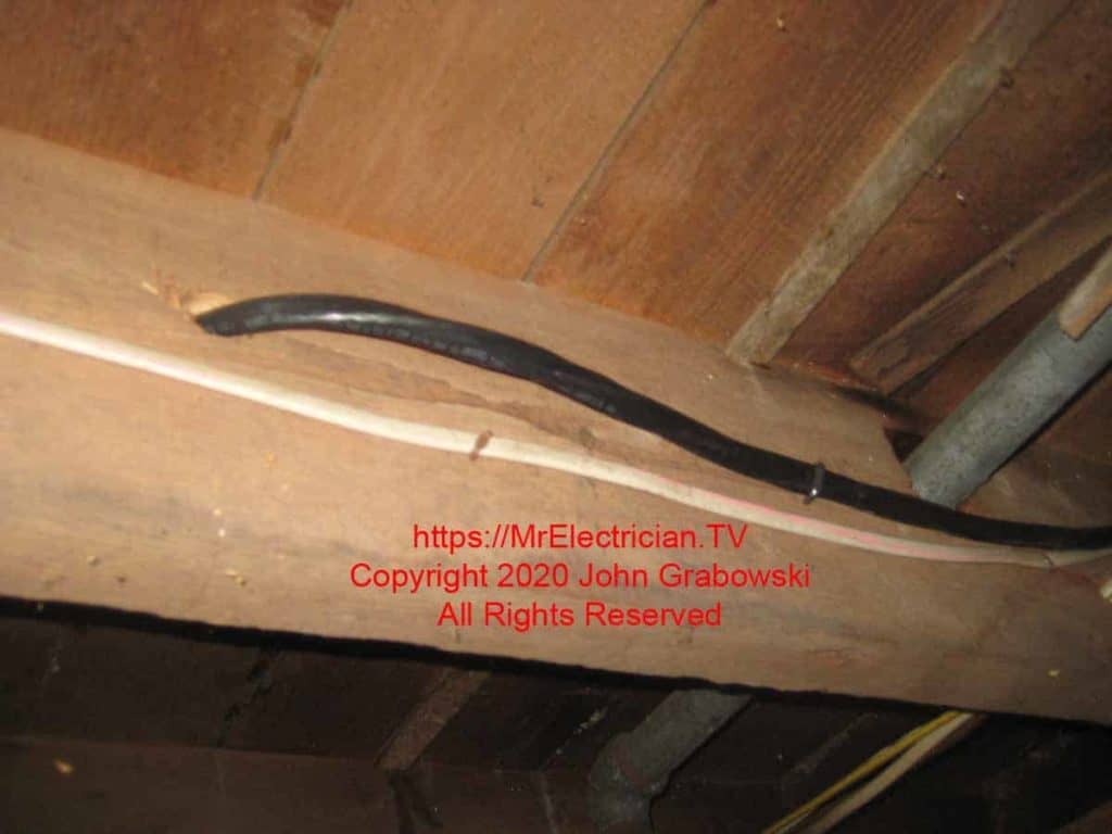
I used 6/3 Type NM-B cable as the feeder cable from the generator inlet to the generator sub-panel. Above is the 6/3 passing through a floor joist on its way to the outside generator inlet. I used my Milwaukee angle drill with an auger drill bit to drill through the joists.
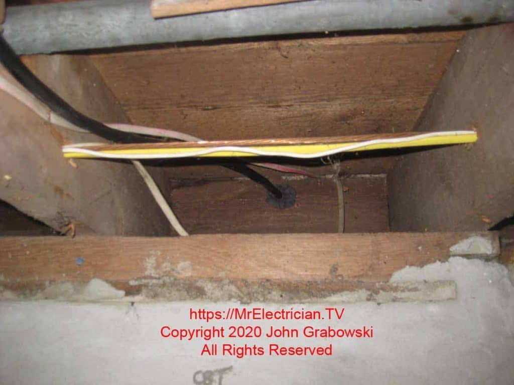
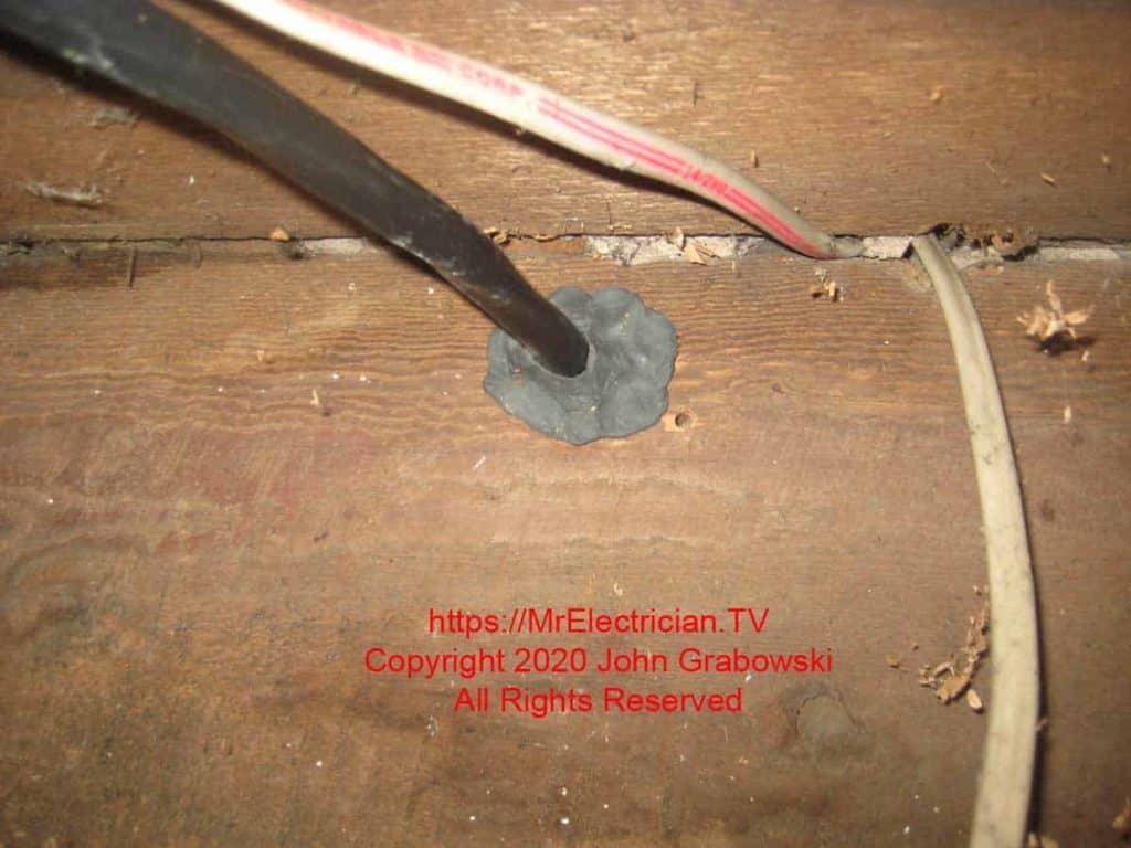
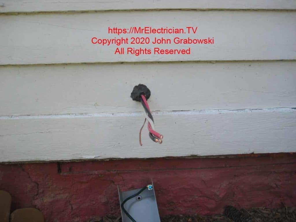
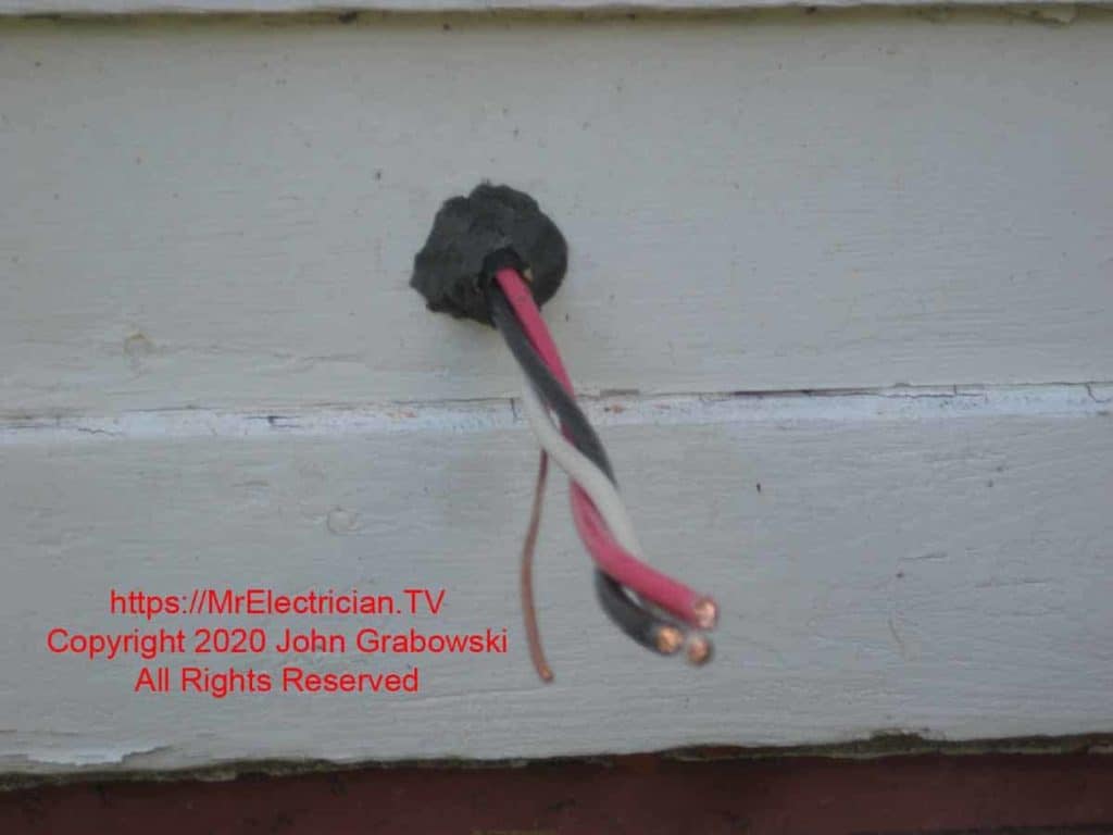
The photo above shows the 6/3 cable as it penetrates the rim joist. On the other side is the back of the generator inlet. Duct Seal was used inside and outside to keep air from moving in or out.
To drill through the rim joist, I first drilled a pilot hole with a long bell hanger drill bit from the inside out after measuring three times to ensure I was in a good spot. Then, I used a hole saw on the outside siding to make a clean-cut hole and not damage the siding.
After drilling with the hole saw through the wood siding, I used an auger bit through the hole made with the hole saw to go through the rim joist.
