Dear Mr. Electrician: How do I install a grounding rod as part of the grounding electrode system for my house? An electrician told me that the grounding electrode system for my home did not have a good grounding rod and gave me a ballpark price to fix it up. Why do I need this, and what is involved in fixing or installing a grounding rod?
Answer: Keeping the grounding electrode system in your home in good condition is very important. To install a ground rod, some tools and muscles will be needed.
NOTE: Some text links below go to applicable products at EMP Shield or Amazon. As an Amazon Associate, I earn from qualifying purchases. Using my links helps to keep this website FREE.
A ground rod is a critical component of the electrical wiring in your home or place of work. It is part of the grounding electrode system for voltage stabilization and lightning protection. A ground rod is also referred to as a grounding electrode or anode. It is required by article 250.53(D)(2) in the National Electrical Code (NFPA 70).
The power company has its power transformer grounded with at least an eight-foot grounding rod. If the neutral conductor from the transformer to your house ever got disconnected, the returning current would travel through the Earth to return to the transformer.
In addition, when lightning strikes on or around your home or workplace, the rod creates a path for the high voltage electrical charge to go directly to the Earth and avoid causing damage to your home.
Whenever you hear of someone’s house getting struck and damaged by lightning, it is usually because the grounding electrode system was deficient.
Table of Contents:
- Components of Grounding Electrode System
- Upgrading Your Earth Ground
- How to Install a Ground Rod
- Connecting Other Utilities to Earth Grounding
COMPONENTS OF A GROUNDING ELECTRODE SYSTEM
The grounding electrode system consists of a wire or two originating on the grounding terminal in your main electrical panel or disconnect switch. The wire(s) from the grounding terminal will connect to the home’s water pipes and one or more grounding electrodes.
The grounding electrodes can be ground rods, concrete-encased rebar, copper plates, copper wire in the footings, concrete-embedded steel, or other means that provide an approved electrical path to Earth. See article 250.52(A) in the National Electrical Code.
Many houses’ primary grounding electrode system connection is at the metal water pipe at the point where it enters the home before the water meter. Look at this area, and you should see a copper or aluminum wire: bare, insulated, metal armor jacketed, enclosed in conduit, or taped green. It should be connected to the water pipe using an approved ground clamp. The connection should be tight and free of corrosion.
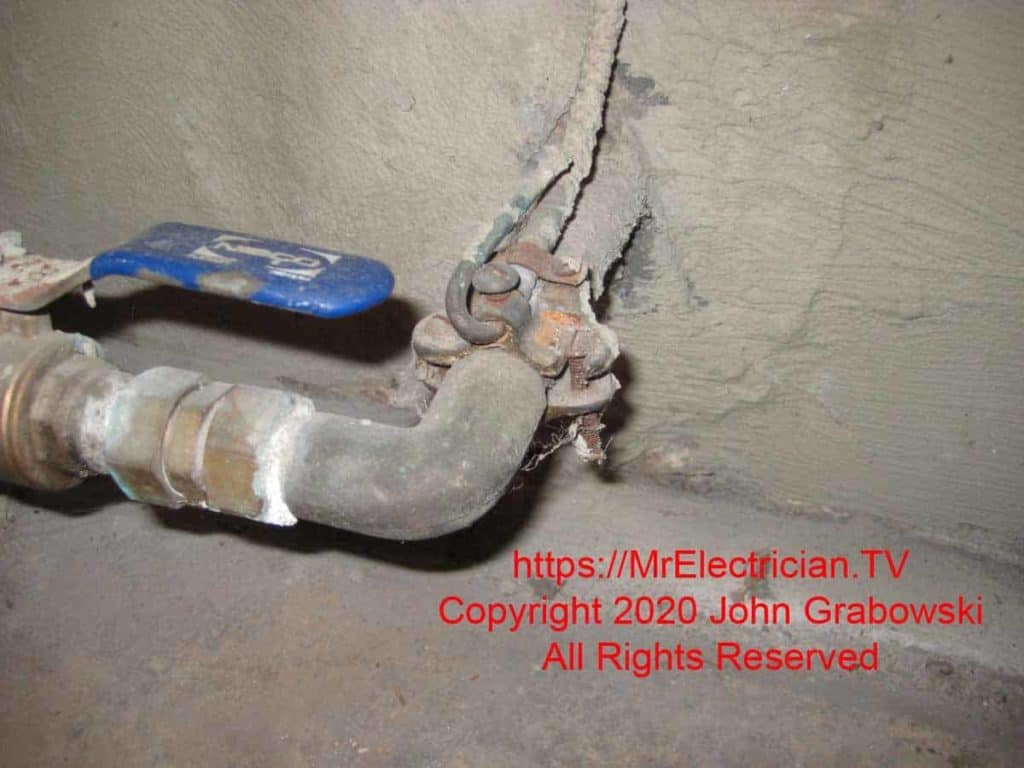
The ground clamp in the above photo is attached at the point where the water pipe enters the basement. An armored grounding conductor requires a ground clamp with an extra clamp for the armor to be secured.
If the ground clamp and wire appear corroded or loose, you should remedy this immediately. A new ground clamp costs only a few dollars and can be purchased at any electrical supply company and many home improvement stores. You will also need some emery cloth or sandpaper to clean the pipe.
A reasonable precaution would be to shut off the main circuit breaker or pull the main fuse in your electrical panel. A tiny amount of current may be traveling over your grounding conductor. I also suggest wearing leather or electrically insulated gloves and avoiding touching the bare wire and the water pipe simultaneously.
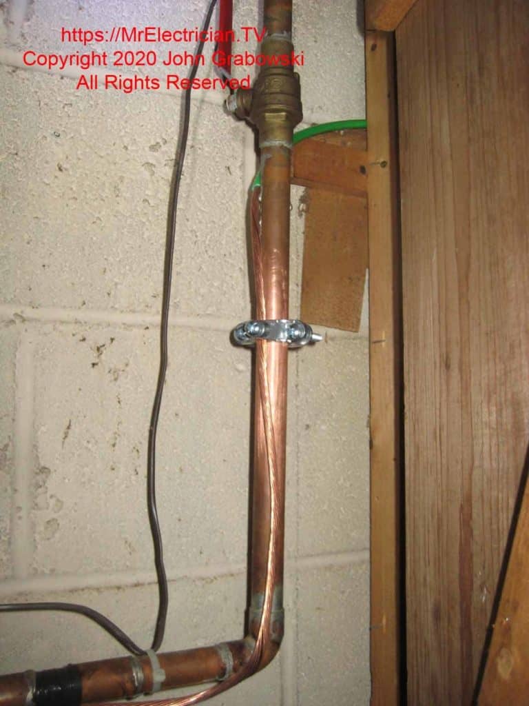
If your home gets water from a private well or a plastic pipe, your primary ground connection may be a ground rod or two. In many cases, the ground rod(s) are entirely buried and therefore are not easy to inspect. According to published data, a copper-plated ground rod can have a life expectancy beyond 40 years.
When working on client’s homes and other buildings, I have discovered loose ground rod clamps, incorrectly installed ground rod clamps, ground rods that have not been driven entirely into the Earth, cut grounding electrode conductors, ground rods that have been damaged from landscaping and construction excavation, and short galvanized pipes driven in the Earth instead of an approved ground rod.
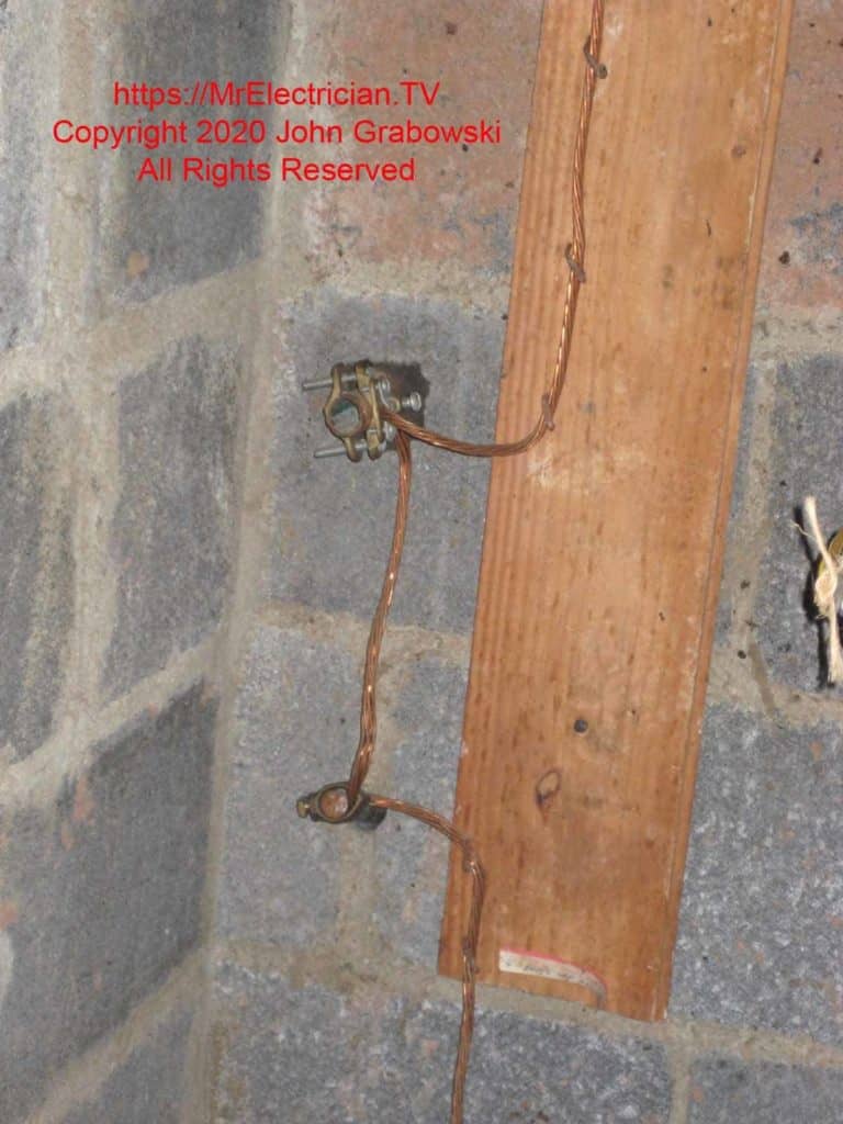
Below is a photo of a ground rod installed through a basement wall, and the grounding electrode conductor is also connected to the old water service pipe. I have installed ground rods through basement walls and basement floors, too. It can be very convenient; however, be careful if the area is known for flooding, as the hole in the wall can allow water to come through.
Something to consider at this time is upgrading your grounding electrode system to the latest “National Electrical Code” requirements. The current code requires that new installations have at least one supplementary ground rod installed and all interior metal piping connected (Bonded) to the grounding electrode system.
Some jurisdictions have waived the requirement to bond the interior gas pipes as part of the grounding electrode system. Check with your local electrical inspector for the correct procedure regarding articles 250.104 (A) and (B).
A bonding jumper wire is also required from one side of the water meter to the other to maintain ground continuity on the metal pipe if and when the water meter is replaced. Read article 250 in the latest “National Electrical Code” edition for all the requirements.
UPGRADING YOUR EARTH GROUND
To bring your house up to today’s earth grounding standards, you will need the following: Five, six, or maybe more ground clamps suitable in size and compatibility with your metal water pipes, gas pipe, water-heated pipes, and any other interior metal piping, two 5/8″ x 8′ copper clad ground rods, two acorn style clamps for connecting a wire to the ground rod, #6 or #4 copper wire bare or insulated, 3/8″ one hole straps, an approved connector for the grounding conductor to enter the electrical panel (In my state we can use a Romex plastic button connector).
I also have green electrical tape if using insulated wire, a ground bar for the main electrical panel if there is no empty slot for a large wire, an “Intersystem Bonding Termination,” and suitable staples for fastening the ground electrode conductor wire.
Additionally, you will need the following tools to facilitate the installation of your upgraded grounding electrode system: A claw hammer, a 3-pound or heavier hammer to drive ground rods, emery cloth or sandpaper, flathead screwdrivers, and heavy-duty wire cutters or lineman pliers, an adjustable wrench, and a six-foot ladder.
You may also need an electric drill and drill bits suitable for drilling through floor joists, a hammer drill, masonry drill bits to drill into masonry, and a flat metal file. A rotary hammer with a ground rod driver attachment will make driving the ground rods into the Earth much easier and quicker.
An alternative is a 35 or 40-pound jackhammer where the ground rod can be inserted directly into the bit holder. Soil conditions determine the ease at which the ground rod goes into the ground.
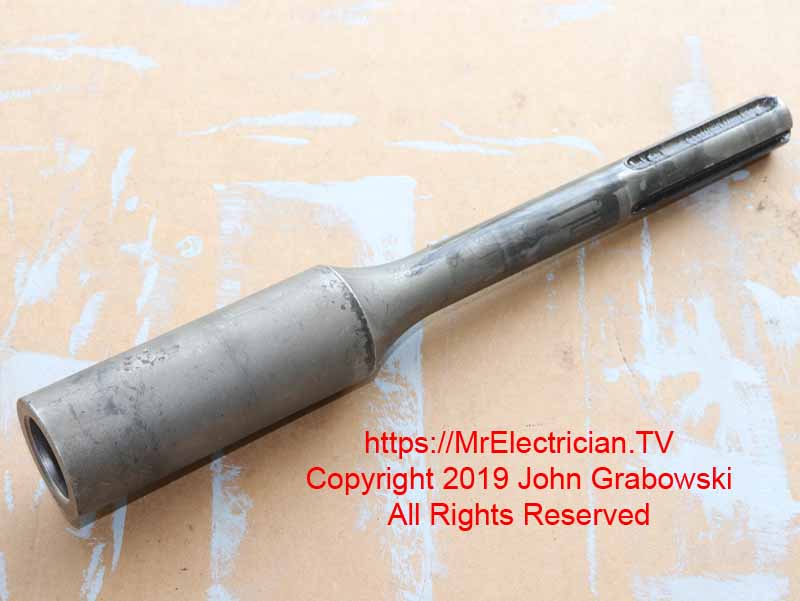
The most challenging part of this job is driving the ground rods. Although one ground rod is the minimum standard set by the “National Electrical Code,” two are often required due to soil conditions.
Soil resistance varies across town, county, and state lines. Without expensive, detailed testing of your soil, there is no way to determine if it has a low or high resistance to electrical current. Therefore, it is better to drive two ground rods to be safe.
Eight-foot ground rods should be installed no less than sixteen feet apart for optimum performance, and there is no maximum distance restriction. Ten-foot rods should be at least twenty feet apart. Please note that the “National Electrical Code” minimum requirement for ground rod spacing is six feet. See article 250.53(A)(3).
Start by choosing an area near your electric meter free of underground electric, water, gas, telephone, oil, irrigation, and other utility lines. Call 811 to arrange a markdown of the area if you suspect underground utilities are buried in the Earth.
Stay close to the house but at least a foot away to avoid contact with the concrete footings. Remember to run a wire from the ground rods to your main electrical panel. You can also drive the ground rods through your foundation wall or basement floor if that suits you. You will need a rotary hammer drill and a long 5/8″ masonry bit to drill starter holes.
Before proceeding further, plan how to drive the rod into the Earth. Generally speaking, the ground rods would be driven straight down into the Earth, with the top slightly below the surface. You can also drive the rod at a slight angle, but using a rotary hammer or jackhammer at an angle can be precarious.
A continuous #6 or #4 wire would be run from one ground rod to the other without cutting or splicing and then directly into the main electrical panel to be part of the grounding electrode system.
If your main electrical panel is in the basement, you must drill a hole slightly larger than the wire (7/16″ -1/2″) into your foundation wall or your siding near where it meets the foundation.
Dig a hole approximately one foot deep to insert each ground rod. The holes should be one to two feet away from the foundation to avoid contact with the concrete footings of your house. Then, dig a shallow connecting trench close to the foundation between the ground rod holes.
The trench facilitates the connection of the un-spliced continuous grounding electrode system conductor from one ground rod to the following ground rod and then to the main electrical panel.
Alternatively, you can run a wire from each ground rod directly to your main electrical panel (As per 250.64(F)(2) in the National Electrical Code. Instead of trenching, you could also attach the wire to the side of the house.
INSTALL A GROUNDING ROD
Take one of the eight-foot ground rods and insert the pointy end into one of the holes you have dug. Stand on a ladder and hammer it down into the Earth using a 3-pound or heavier hammer in one hand while holding the ground rod with the other. An assistant would be suitable for holding the rod as it tends to move around and vibrate. It will probably go in easy at first, but after a while, it only sinks in a very short distance with each hammer blow.
This would be an excellent time for a rotary hammer drill with a ground rod driver attachment or a jackhammer, as depicted in the photo below. After you have one ground rod driven, proceed to the next one.
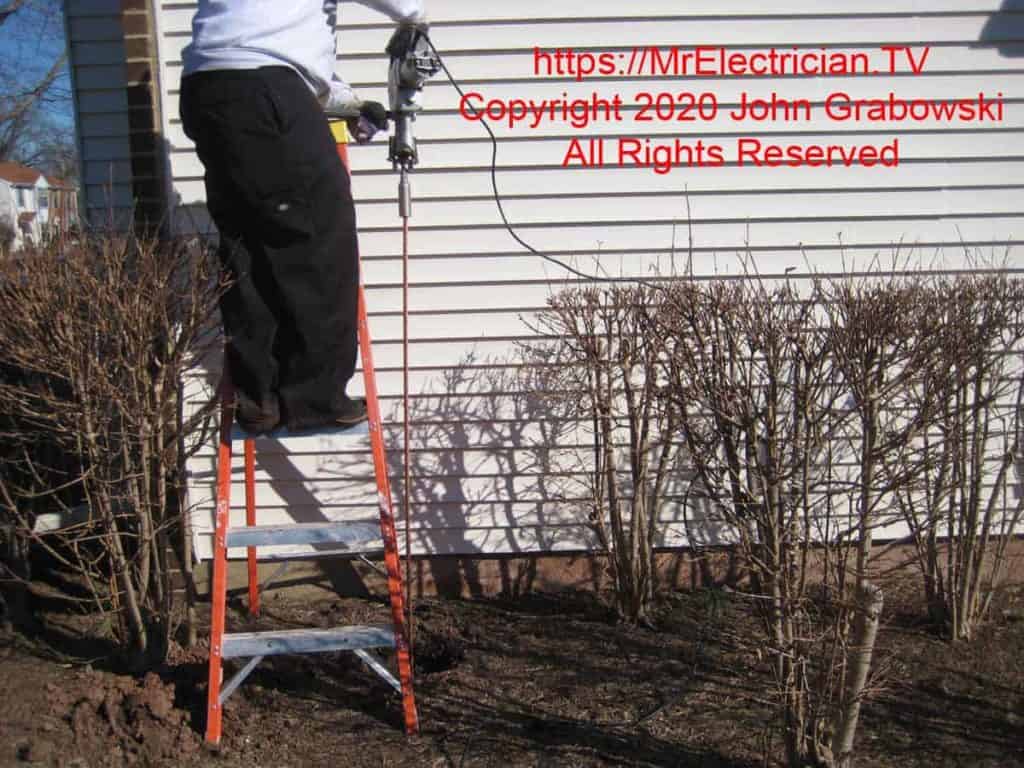
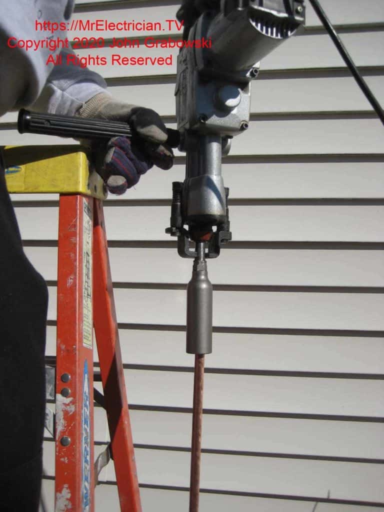
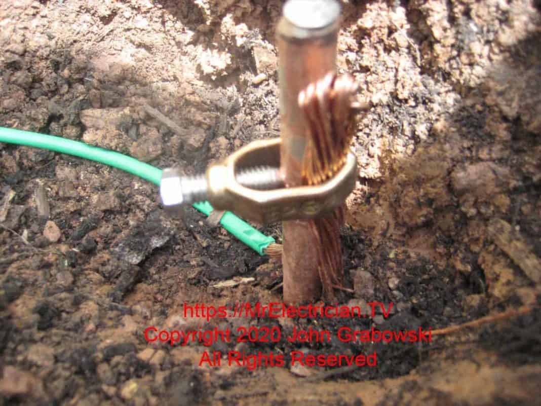
Once the ground rods are slightly below the Earth’s surface, you can attach the copper wire using the acorn-style ground rod clamps. Depending on the circumstances, starting from the main electrical panel’s location and running the wire to the ground rods may be more straightforward.
CLICK HERE to see Ground Rod Drivers for sale on Amazon
Run the wire through the trench to the ground rods and put it through the acorn clamp with the wire between the clamp and the rod. Do not put it between the clamp screw and the rod.
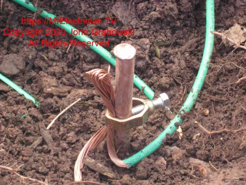
I usually strip 4″ – 6″ of insulation off and double the grounding electrode system wire over to make good contact with the ground rod. Bring the wire into the house through a small hole in the foundation or siding and continue to the main electrical panel. If you are running this in a basement and need to cross some joists, you should drill small holes in the center of each joist and run the wire through the joists instead of under them.
The wire should be secured every 3′ – 4′ using cable staples if installed on the side of a wood joist. If you are using insulated wire, though not required, it is a good idea to wrap green electrical tape around it in a few visible areas so it is identified.
The final connection is inside the main electrical panel. Bring the grounding electrode conductor into the electrical panel through a 1/2″ trade size (7/8″ actual) hole using a connector approved for the grounding electrode system conductor. Sometimes, the inspector will accept a clamp-type metal 3/8″ squeeze connector or a plastic strain relief button. Each wire must be terminated in a termination screw.
If there aren’t any available screw terminals, then you will need to add a ground bar with terminating screws in the main electrical panel. After marking, drilling, and tapping two holes (Usually 8/32), screw the additional ground bar directly to the metal enclosure of the main electrical panel using fine thread machine screws.
Do not use sheet metal or wood screws to secure the ground bar to the electrical panel. It has been determined through laboratory testing that a minimum of 2 1/3 threads contact must be made to ensure proper grounding.
GROUNDING of OTHER UTILITIES
Article 250.94 requires an “intersystem bonding termination.” A means must be provided for other utilities, such as telephone and cable TV, to attach their separate grounding conductor to the grounding electrode system. This must be located near the electric meter.
Several manufacturers have products to quickly meet this requirement by attaching it to your grounding electrode conductor and fastening it to an outside wall or the electric meter. When installing your grounding electrode system conductor, leave an 8″ – 12″ loop in the area of the electric meter for this terminal block to be installed later.
Other intersystem bonding terminations attach to the electric meter base or directly onto a ground rod.
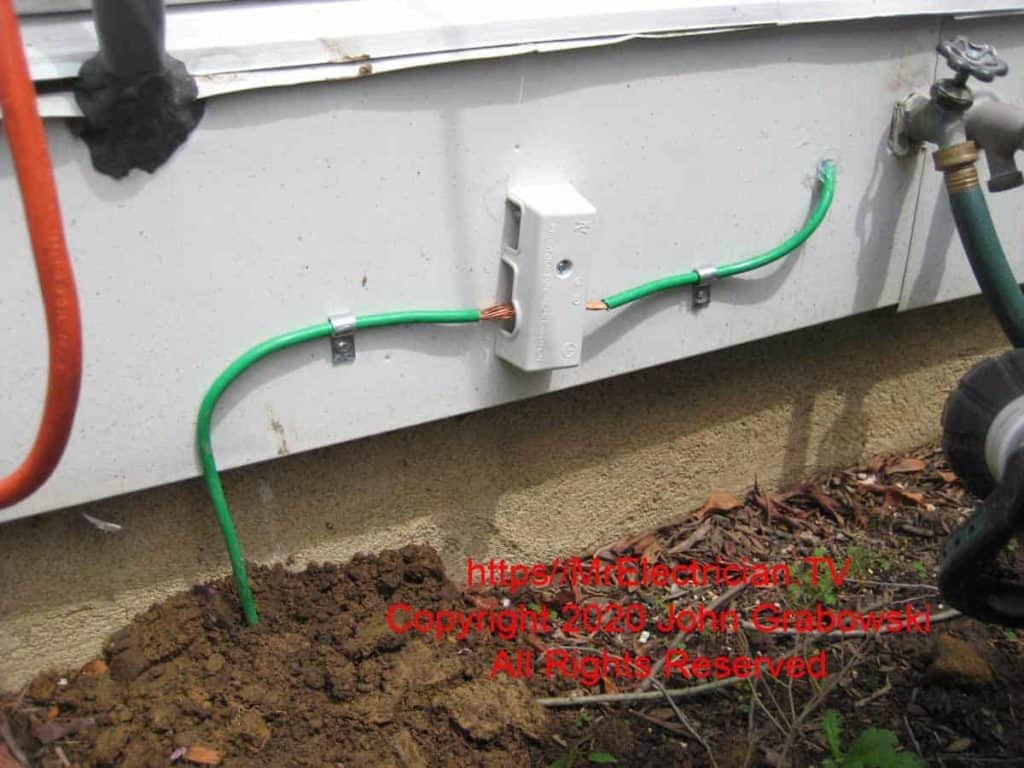
To fully protect your home against lightning, the cable TV and telephone service must be bonded to the intersystem bonding termination. Use a #10 copper wire to connect the cable TV and Telephone service at its entry point.
There is usually a screw terminal on the cable splitter or termination point for grounding purposes. The telephone demarcation point or box should also have a grounding terminal. Look for a green screw or a lug.
Like any roof-mounted TV antenna, a satellite dish antenna should be bonded to the intersystem bonding termination.
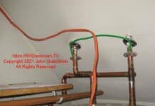
Lastly, a bonding jumper must be installed between your hot and cold water metal pipes using water pipe ground clamps and a piece of #6 aluminum or #8 copper wire. This can be done at any point along the piping system but is commonly connected to the water heater so that the electrical inspector can see it.
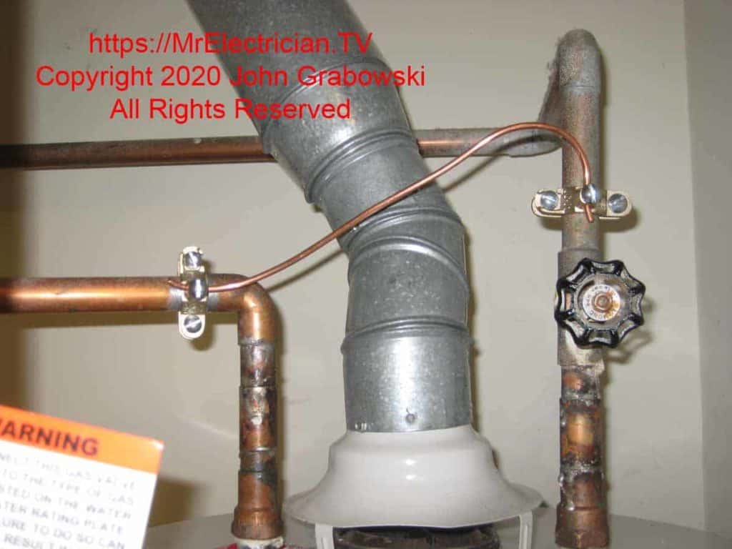
Bonding to the ground rods is necessary to prevent lightning damage to your home. Lightning wants to go to Earth, but sometimes, things get in the way and are sacrificed. By providing a good solid path to Earth via the grounding electrode conductor and the ground rods, you are minimizing the damage that could occur.
The lightning strike that does damage may not hit directly on your home. It could hit a telephone pole across the street and travel down the utility wires until it finds a path to Earth.
An additional enhancement and level of protection can be made to your grounding electrode system by installing a whole-house surge protector. This gets wired directly into your electrical panel and is connected to a dedicated two-pole circuit breaker.

Beginning with the 2020 National Electrical Code, a surge protection device connected to the grounding electrode system is now required to be installed on the service of a house. You can read my article about surge protectors here.
Click here for my photos of grounding and bonding for TV, Telephone, and Power as part of the grounding electrode system.
All my grounding, bonding, and surge protection articles can be seen here.
To help keep this website FREE, please use this Amazon link for your purchases. As an Amazon Associate, I earn from qualifying purchases.
Click for a FREE copy of my book “Almost Everything You Need To Know To Repair a Bathroom Exhaust Fan In Your Home.”
Get your required “Emergency Disconnect, Service Disconnect” labels and stickers to satisfy the 2023 National Electrical Code requirements in article 230.85(E)(1) and (2) by going to my Redbubble Shop here.
Visit my Link Tree for free electrical information, stickers, supplies, merchandise, and social media links.
